
As can be expected, the construction of the Statue of Liberty was a long and costly project. This project originated in a public meeting held April 21, 1865 at Glatigny (Moselle, France). The participants were in love with the young republic of the United States and celebrated as the anniversary of the abolition of slavery. It was during this meeting that was proposed the construction of a colossal statue to reinforce the Franco-American friendship. Auguste Bartholdi, a young artist and architect, attended and offered himself to divert the project he had already done for the creation of such a statue at the entrance of the Suez Canal. This was adopted. All this is told in the Origin of the project.
This was done. The financing part was quite difficult to complete, both in France and the United States. This project required the
intervention of the two countries because if the statue is a purely French construction, the gigantic pedestal, it is the responsibility
of the host country. So two fundraising campaigns that have been launched in parallel, and he came very close to the project can not be born.
This is also told in the Funding section of the Statue of Liberty.
The project
Once the project is launched and funding secured, Auguste Bartholdi and Gustave Eiffel were able to tackle the technical part. We must separate the two works: The artist Bartholdi was committed to the realization of the outer shape of the statue, while the engineer Eiffel conceived the internal structure of the statue. It's two completely different businesses that have been implemented in different places by different workers.
These manufacturing work began in 1876 and were completed in 1884. They were in response to the fundraising campaign which lasted 5 years (1871-1876). Completed in 1882 the pieces were assembled, the complex was completed in 1884 and remained a year in central Paris. Then in 1885 the statue was dismantled before being sent to New York.
Pedestal Construction
In parallel with the construction of the statue was built in the US stand, a gigantic slightly higher pedestal for the statue itself, with an antique style. The description of the base and the history of its construction is on this page.
Construction of the statue
Model design and expansion

The expansion of the original model
The expansion of the original model
The model of 2m corresponding to the first expansion of the initial model, preserved in the Musée des Arts et Métiers in Paris.
The first thing that Bartholdi made a model, small size (1.20m). This model was made some years ago to show the project concretely. But this is not because Bartholdi had made a model of a twenty meter he could easily bring it to 45m, expansion could not do so easily. It is passed through two intermediate models, one of 2m and 11cm, made to scale 1 / 16th, then the other of 8m50, which made a reduction to a quarter. They were both plaster It is the latter model which served the final expansion. It had to be cut into 12 pieces so it was great and it is these 12 pieces that were restored one by one copper. To be sure of its proportions the artist took many measures throughout the work. In total there were 9000 identified points of agreement between pieces by its model and the actual statue points he adapted regularly as once enlarges the model could differ from expected results. The model of 2m40 is currently at the Museum of the Quai d'Orsay, he was initially in the gardens of the Luxembourg Palace but it was in the process of thawing is why the palace was proposed at the museum, to protect it.
To get to the final dimension, he used copy method by tiles. The model to 1 / 4th, after review and remodeled by the artist, was divided into section. On a square base 4 times larger than the model on which he turned exactly all vertical plumb of the statue, spotted plummet. He thus obtained, in a way, a virtual volume constituted by all vertical lines marked inside which the statue is located, or a portion of the statue on an enlarged scale. It is then possible to determine the main points of the modeling from these vertical lines by practicing horizontal sections in the statue quarter. This is the same process that is used to find the contour lines on a map. These sections are reproduced in four times larger. Each section was reproduced on a horizontal base and used in the design of the plaster mold, which will be discussed below.
Full size mold manufacturing
The technique of manufacturing practice of the Statue of Liberty has followed an original method and long enough to implement. Simply put, for every part of the model he make a wooden structure approximating what to get, and then it was coated with plaster that structure. He worked plaster until its measurement points correspond perfectly to sections previously measured, and it was making the same shape but made of wood, a much more solid than plaster. Once created wooden model, the workers had only to be hammered copper plates which then took shape.
It was necessary to start with the construction of the wooden structure. For that Bartholdi used wooden battens fairly large section that had set on beams a solid wooden frame as a basis for the structure. This base was to be able to support all necessary manipulations, she had to hold the weight of several men and more natural weight of plaster, ie strength. On this basis the wooden battens were fixed every 5 cm or less, ranging form the artist approached what he had planned for the play at runtime. Once finished it looked like an original form of wooden cage.

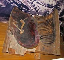
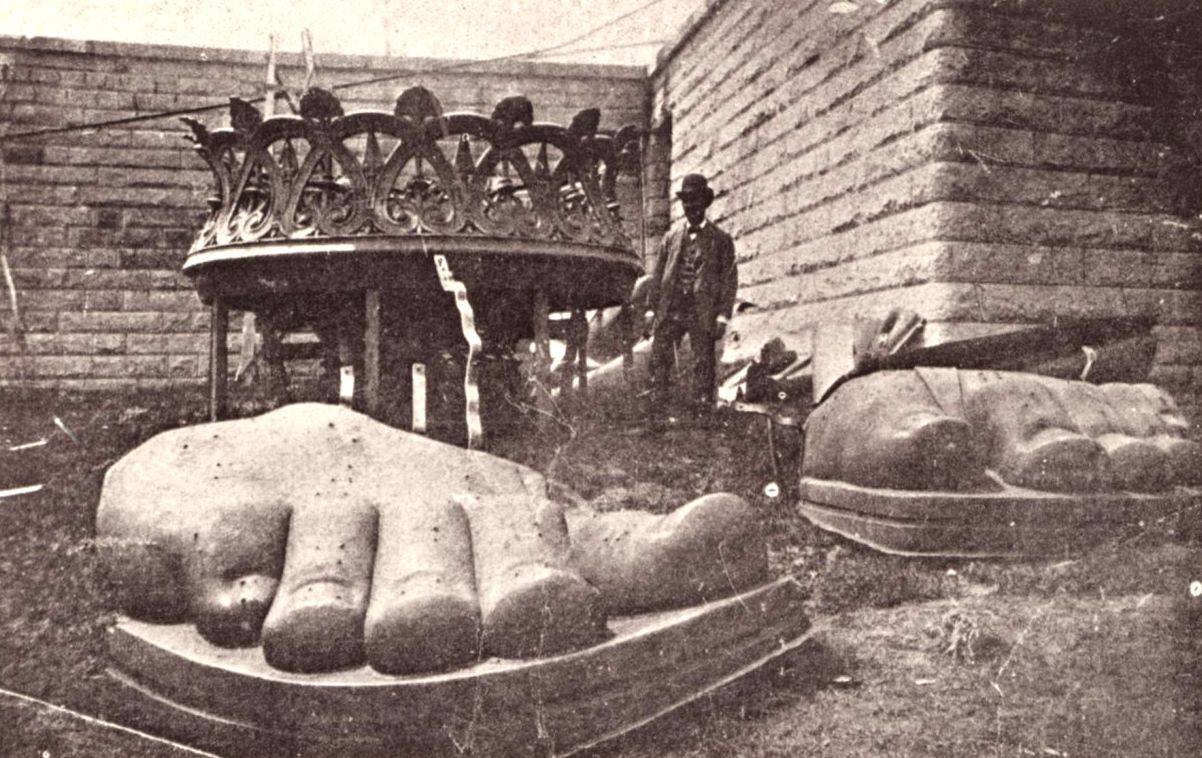
The hand of the statue
The hand of the statue
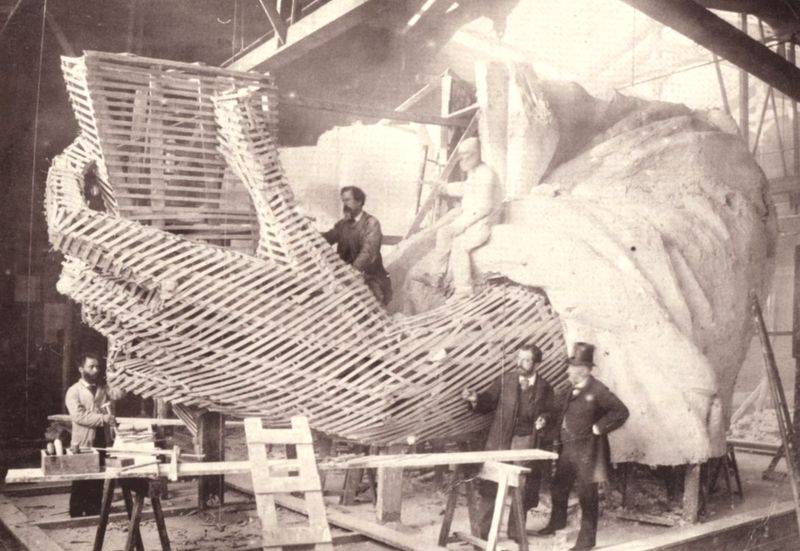
Cast of the hand of the statue, on a wood frame.
This image shows the wooden structure made from battens used for plaster cast of the hand of the statue, the one that holds the tablet. When each component was over the plaster was broken, the wood frame was destroyed and the cleats were used to mount the next section.
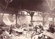
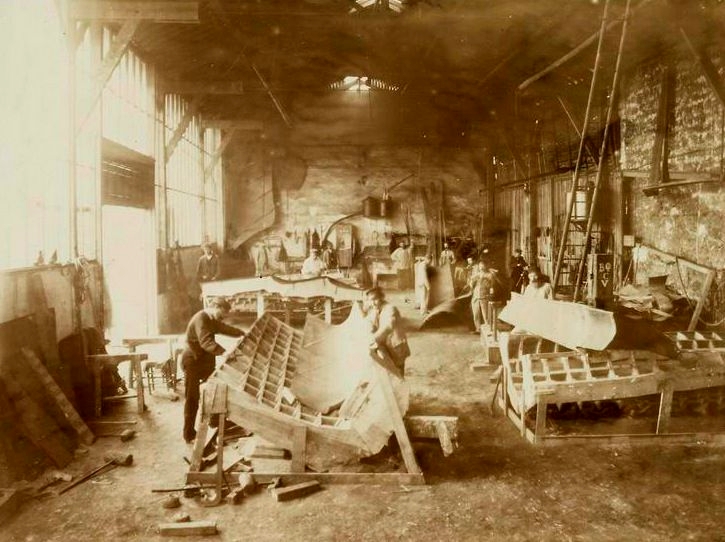
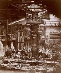
Workshops Gaget
Workshops Gaget
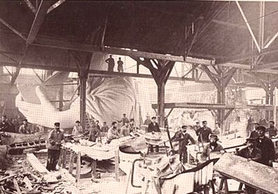
Overview on Gaget workshops, open-work construction of the Statue of Liberty.
As work progressed, it was the place. The workshop has always been big enough to accommodate both the copper plates not worked, the finished parts awaiting installation, the final structure mounted partially and work tables of workers. The organization was pretty strict. In the background of this photo we see the hand of plaster molding, which follows the wooden structure. At the junction between the hand and the toga we still see the cleats.
The next step required the intervention plasterer that covered the structure of a large quantity of plaster. The layer should be strong enough to allow measurements but it was useless she too: She heavier overall and was undermining. The plaster work was essential. Once solidified it was sanded, cut, modeled until each of the items in sections perfectly match the measurements of the model. The use of the plumb line was paramount, this precision work probably the most important. Very simple as theory this method required a certain skill from the performers. Each nail head or run scored 6 measures required, one per dimension for the model, by another dimension for the enlarged replica, not including verification measures. The parties having approximately 3m40 in height and in every part have 300 main points and secondary points over 1200, each party must be required over 9000 measurements, which is still phenomenal.
Manufacturing template

A wooden template
A wooden template
Engraving reproducing a wooden jig for hammering copper plates.
The plaster model workers intervened to finish the construction of a wooden template, faithful reproduction of the plaster model. The plaster model had no other function than to serve the realization of wooden template, to be completely identical. This part was rather long to do and used a lot of wood. The carpenters were working forms until the template is considered sufficiently close to the model by Bartholdi. It was a complicated carpentry work presenting difficulties similar to those encountered in the study of foundry molds. Like these, the templates must be so constituted that can be easily detached from the model. Then you can make the body, ie remove the copper sheets that will be stamped. To the template was used wooden boards laid in field square. Then they bind them with other boards, as would shelves in a rectangular cabinet. Finally we added other boards transversely in roughly positioning the close of each other depending on the desired accuracy for the room to pound. The boards were advancing more or less, highlighting shape as contours. These templates were larger or smaller, depending on the difficulty of the work. Sometimes in several assembled for the adjustment of the copper sheets.
hammering
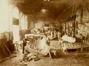
Workshops Gaget
Workshops Gaget
The workshops were Gaget in central Paris in the late nineteenth century.
This photo shows one of the workshops during the hammering copper plates. It segregates the small thickness of the plates, their sizes, actually quite modest. This is normal, it was necessary that workers can handle quite easily for work.
Next comes the copper plates of the shaping phase. These plates are 1 to 3 square meters, we could not find more than 1m40 wide. They are worked into force by hammering on the wooden template. In total the statue weighs 88 tons and consists of 300 plates, of which the first 64 were given by industrial, allowing the construction to begin. At 88 tons must be added the 130 tons of framework of Eiffel, making a total weight of 220 tons. The plates were brought on the template, shaped by pressure lever or hammered wooden mallet, then returned on huge work tables to be refined before returning to the gauge whether refining was correct. There were several round trip per plate before it is considered correctly modeled. The finish was made on the tables by beating the little hammer and rammer. For pieces having shapes very pronounced the copper plates were heated somewhat to facilitate hammering, becoming more malleable. The really hard plates were run past the forge fire and were brazed torch
A hammering jig
A hammering jig
The template that was used to shape the ear of the statue. It is the museum of the statue.
The penultimate stage was that of verification. Before discarding a plaster model Bartholdi was pouring lead on the plaster. Lead is extremely malleable, it was easy to spread over the entire shape and draw a pattern. This lead model was superimposed on the copper plates that were in perfect fit. Otherwise the plate had to return to hammering to correct the defect, which was rather small but real. Some models were verified mesh wire, just as malleable. The finished part was passing to other workers who had to polish the charge plates and then adjust them to form a single element of the statue. Here and copper coins were furnished with fittings designed to give them rigidity. These fittings were forged from the form of copper, when it was completely modeled, but were fixed in the amount statue.
Note: Most of the photographs below were taken by Albert Fernique.
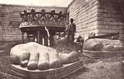
The base of the statue
The base of the statue
The foot of the statue being assembled in the workshops and Gaget Gauthier
Throughout the construction of the various elements, they were stored in the yard and workshops Gaget Gauthier.
The arm and the torch
The arm and the torch
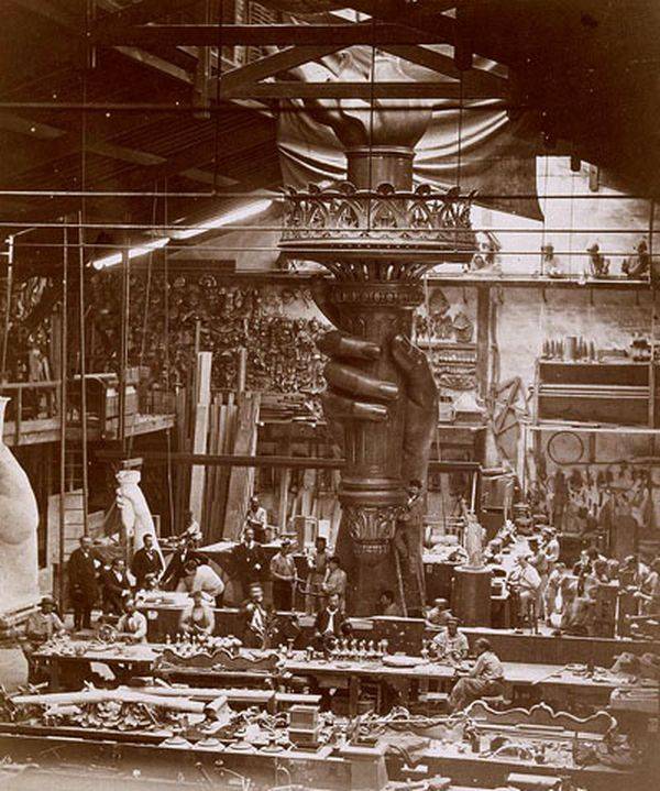
The arm of the statue in Gaget workshops.
An essential element of the statue, the famous torch. We see that her neck is very worked and nails are more detailed than it appears today. This photo also shows the workers at work, working alone most of the time pieces. A carelessly left some personalities pose for a picture.
Head of the statue
Head of the statue
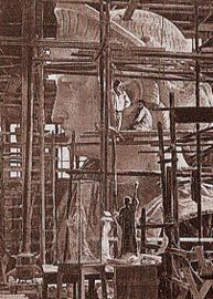
The head of the statue, in Gaget workshops.
Once assembled head occupied a large part of the workshop. It was awesome and did not yet have the seven rays from her head. The workshop was just high enough to assemble, but this detail was anticipated at the time the choice of the construction site.
Assembly
The assembly of the copper plates had to be done twice. Once during installation "blank", in Paris, a second final in New York. Of course there was no question of damaging the copper plates at the Parisian assembly-disassembly before sending them to the United States. So we used simple screws for initial assembly, screws that were replaced during the final assembly by rivets 5mm thickness remote from each other of 25 mm. As the pieces are juxtaposed bevel it becomes impossible to distinguish the junctions, even at close range, and the statue appears to have been mounted in one piece.
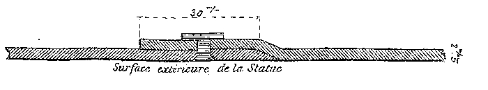
Speaking of juxtaposition, we must know that the plates that making only 2.3mm thick, they were in fact only 1.2 at the edges, to allow their nests. The edge was still 30cm, making it a lot. Here is the explanatory diagram of the assembly of two copper plates.
Electrical phenomenon
The Statue of Liberty is not electrified, in the sense that the electrical system is only used to illuminate the inside of the statue to visitors. But there is still an electrical phenomenon known craftsmen working metals, phenomenon that takes a completely different magnitude in the case of a colossal statue. This is the electric action whose effects are to be feared. The sea wind, which always leads mechanically and independently spray, high proportions of salt water to the vesicular state, is one of the most active agent for the spontaneous creation of electricity from an iron-copper element such than that resulting from the construction of the statue. Recall that the internal frame is made of iron, the outer covering of copper, so there has contact points that will generate that electricity. This phenomenon can also occur in the presence of rainwater storm charged with nitrates. One can easily judge the intensity of the currents that take birth in an element of this battery of a relatively large power given its size. To prevent manufacturers have interposed upon final assembly of small plates of copper lined with rags properly coated minium between the copper sheets and iron frames. This method is successfully used by the Navy for dubbing ships. It could even be used as a generator!
Construction delays
Bartholdifaced numerous delays in its construction. In March 1876 an accident broke the plaster cast of the hand. The previous year he sorely missed of skilled labor, but to deceive the Americans he send a first element to present to the public, it was the arm holding the torch, and that during the Centennial Exhibition (1876 ). In June 1878 the head of the statue was shown the gardens of the Champ de Mars in Paris for the Universal Exhibition, reassuring the population about it.
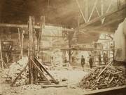
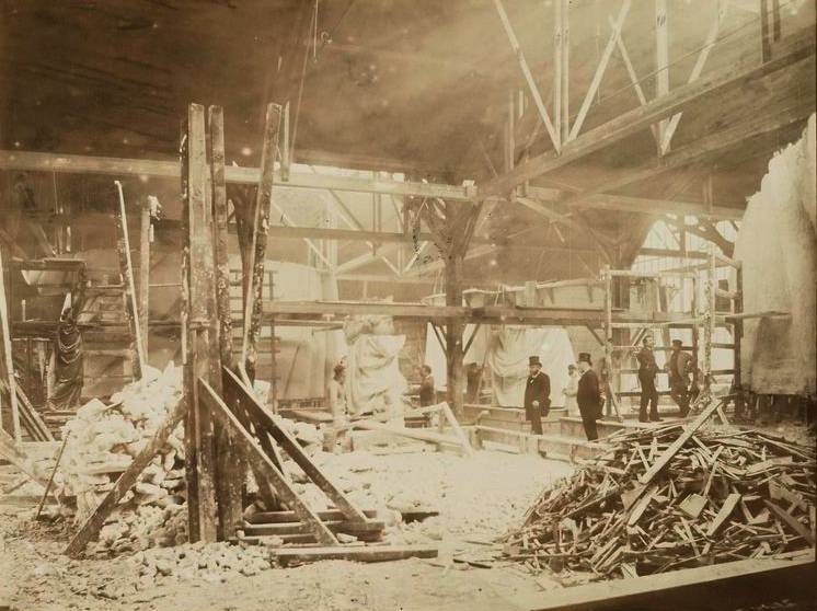
The pictures below show the workshops with the different parts being assembled. The work in the workshops was not as painful as it might be in other workshops. The skilled labor was scarce, this is why Bartholdi took care of its employees. Besides the project was partially slowed because of a lack of personnel, precisely, for a while. You should know that Gaget workshops and Gauthier employed 300 to 350 people, which made it a big workshop in the Paris region.
Workshops "Gaget and Gauthier"
Workshops "Bechet and Monduit" workshops were ironwork well known in Paris. It was they who had made many metal work on Paris, starting with the piping of the drinking water network, the Campanile Hotel des Invalides and some zinc roofs Haussmann buildings. These workshops were bought by gentlemen "Gaget and Gauthier", two entrepreneurs who kept the hundreds of workers who were in their provisions for commissioned work. When Bartholdi chooses to work the copper plates of the Statue of Liberty they had both a sense of pride for their participation in the project for which the French were mobilized, but also worried because the work required special skills that they did not necessarily available. They just deliver the dome of the Opera Garnier in Paris, a command of Napoleon III.
The workshops were located north of Paris, in an area of wasteland on the edge of warehouses, not a particularly pleasant place to live. Parisians avoided this remote location of the center, much more enjoyable. Nowadays it is a posh neighborhood in the center of which we find the Parc Monceau. If one has pictures today it is because Bartholdi had felt that her statue would interest the French and asked a photographer to follow the work. This is important work that allows us today to present the photos of this site. And we see these famous workshops, makes quite classic for the time: The brick walls rise to a height of about 5 to 8m high, a frame of metal beams and roof sheet metal and glass. One of the walls is always made of wood or metal and glass to illuminate the entire workshop. The Gaget workshops and Gauthier were not a single space but a set of separate work areas from each other. Some areas were very large and long, others were smaller. If they were rather crowded but there was no overcrowding in regard to the workers. They were many but not walking over each other, thanks to all this space precisely. The noise was relatively small, there was certainly hammering, but that was the only really painful noise of workshops, let it not resounded all day. Rather, it was background noise, discussion, raised and placed tools noise, movement of various materials, etc. The workshops had a courtyard outside, it is here that were stored the finished pieces, pending their mounts.
Workshops Gaget
Workshops Gaget
The workshops were Gaget in central Paris in the late nineteenth century.
The construction workshop. On the right we see the pile of rafters which was used to build the forms on which the parts were plated once worked.
The Eiffel frame
Choice of the architect
When Gustave Eiffel took over Viollet-le-Duc for the design of the internal structure of the Statue of Liberty, it decided to replace the initial project of constructing a central masonry tower on which would be fixed metal beams a set that which had made a specialty the engineer wrought iron. Eiffel had indeed built many iron bridges forged in the previous decade. He built on her own plans some halls station, including that of Birrh cellar Thuir, near Perpignan, but especially many bridges. Her ingenuity proved that he was right when he abandoned the traditional metal constructions made of massive beams, very strong, supported by central batteries for a very light airy metal structure. Her trick? There were two. First, make one gigantic bridges reach without central pillars, referring forces on natural cells. Then, using light beams, drilled large triangular holes through which the wind passed without endangering the bridge. With these two notions of architecture of Gustave Eiffel bridges are still standing today, for example the Garabit, which passes over Truyère, in the Massif Central. These methods will be used a few years later to build her famous tower in central Paris, but it is exactly the same style of construction that was used for the Statue of Liberty: Light beams able to twist slightly, depending on winds instead of solid massive beams difficult to implement.
If the starting point for Eiffel was granted, the fact remains that it faced some novelties compared to what he was experiencing: Its structure was not an end in itself, such as future Eiffel Tower, but it only served to support another metallic structure, the copper plates Bartholdi. The wind was also almost zero inside the statue when he used to take it into account. But he had to take the same structure without the copper cover, for example during assembly. And then, perhaps is it the most complex, its structure should be capable of supporting a similar but smaller structure: the structure of the arm, which had to be considered as an addition to the original structure.
Technological choices

Model of the structure
Model of the structure
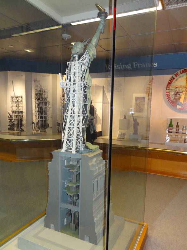
Model of the internal structure of the Statue of Liberty, located in the museum.
Eiffel suddenly saw fit to build its structure around a central tower around which iron spiral staircase. This pylon from these main beams horizontally beams used for fastening other lighter joists. At the end of each of them stared at the engineer iron parts that can slide slightly on the secondary beams. These pieces were equipped with some elasticity, and it is this elasticity which gives the Statue of Liberty, the ability to move slightly facing strong winds. These days will be used instead of plastic parts. This is the anchor of the copper plates on iron girders which is probably what was most difficult, technically speaking.
The other problem was the structure of the arm. Fortunately Gustave Eiffel was a regular in the construction of bridges, so it had already made out additions such as a protrusion at a wrought iron structure. Here he chooses to set a second smaller structure made mostly of secondary beams of various sizes, to fit the shape of the copper plates. The bracing was mastered, and suddenly there was no need to add reinforcements under the arm of the statue which would have spoiled the beauty of the whole. The spiral staircase, once arrived in the head of the statue, went on her way up the torch. It was closed because the platform at the top, was too dangerous.
Constraints
The iron frame, which serves as a fulcrum for the entire envelope of copper, forms a sort of large pylon with four attachment points on the basis of masonry that supports the statue. Each of these points, shaped pad is held by three foundation bolts, 15cm in diameter, sealed to 15 meters deep. The envelope is connected to the pylon via rebars 50mm flat irons on 8mm thick, which are placed on the inner surface of the copper to prevent the deformation. These frames are joined together by bolts at their points of intersection, and are a real lattice resting directly on the frame. Take into account the expansion, which occurs significantly and unavoidably; but this action is without inconvenience due to the extreme elasticity of the envelope and expansion bellows that provides many of the pleated draperies. In addition, for each metal can expand freely, iron reinforcements, instead of being riveted on the image are simply maintained in copper sheaths riveted themselves on the envelope.
Calculation of the iron frame
The frame of the statue was incorporated as a stack, ie it consists of four rafters, size four sides in which are arranged in a lattice struts and cross of St Andrew.
The framework for the statue of iron must be able to withstand two types of efforts: first the actual load and its components, the second horizontal forces exerted by the wind. It is the particular problem of metal lighthouses, resolved by Mr Eiffel in terms of any special difficulty, because of the shape irregularity and construction. Iron, thanks to its elasticity, its relative insensitivity to cold and its ability to resist equally well to the extension and compression, is now generally adopted for this type of constructions. A well combined iron construction, forming a single and homogeneous, can, indeed, as we show below, be subject to the determinations of the calculation in any case, so that there are no unforeseen effects in that may occur on it the strongest hurricane. Iron is undoubtedly even higher in this case, melting which is much heavier, with no flexibility and a still difficult assembly.
The frame of the statue was incorporated as a stack, ie it consists of four rafters, size four sides in which are arranged in a lattice struts and cross of St Andrew.
Plan rafters
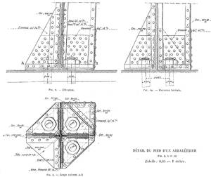
Plan rafters

Plan Playing a foot rafter
In continuation of the rafters are of mooring anchors that go down into the masonry and are fixed to box springs consist of beams. The length of the tie Bases dimensions are determined so as to attract a large enough masonry to prevent the overthrow cube.
The calculation of the frame comprises:
We will consider, in a special paragraph, the calculation of arm holding the torch and which is placed in cantilever across the top.
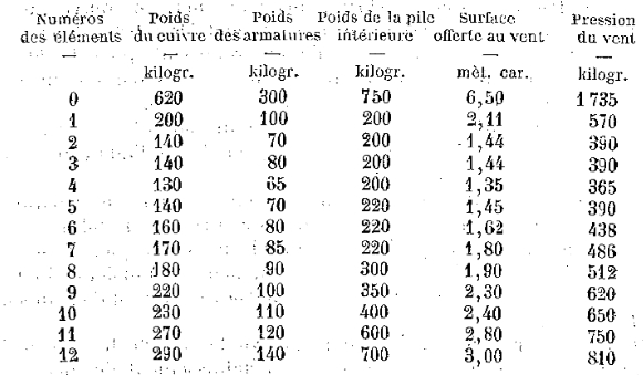
General data:
| Weight of frame | 120 000 Kg |
| Envelope weight | 80 000 Kg |
| Total load | 200 000 Kg |
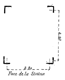
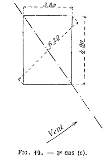
The distance between the rafters at the base is 3m80 on the face of the statue and 4m90 on the sides. The maximum force in the wind, generally adopted in the calculations of viaducts, is 270 kg per square meter presented to the wind; it is this value that was also adopted in this case.
Calculating Archers
The effort from loads of rafter is 200 000 / 4 = 50 000 Kg

With regard to wind loads, there are three cases to consider:
- Wind on the face
- Wind on the side
- Wind diagonally
a. This is the case in which surface submitted to wind , the statue is the largest. The force of the wind is determined by considering bending moments obtained by multiplying the efforts by their distance to the point that we consider and summing these products. Long enough when they made analytically, these operations are very fast when we use the graphical method. This is what has been done in this case.
To this end it was determined on a diagram the projection of the statue in scale 1 / 100th and divided the area resulting in 21 items whose surfaces were measured exactly. By multiplying the value of these surfaces 270 (pressure coefficient in the wind), we obtain the value of the forces acting on each element. The following table summarizes the calculations:
| Item | Area | Strain (Kg) |
| 1 | 4.10 | 1107 |
| 2 | 3.15 | 850 |
| 3 | 3.10 | 837 |
| 4 | 3.40 | 918 |
| 5 | 6.15 | 1661 |
| 6 | 13.20 | 3564 |
| 7 | 15.20 | 4104 |
| 8 | 15.20 | 4104 |
| 9 | 18.80 | 5076 |
| 10 | 24.00 | 6480 |
| 11 | 24.60 | 6642 |
| 12 | 20.40 | 5508 |
| 13 | 19.00 | 5130 |
| 14 | 18.40 | 4968 |
| 15 | 18.60 | 5022 |
| 16 | 18.40 | 4968 |
| 17 | 18.20 | 4914 |
| 18 | 18.00 | 1860 |
| 19 | 18.10 | 4887 |
| 20 | 21.00 | 5670 |
| 21 | 21.80 | 5886 |
| Totaux | 322.80 | 87156 |
This table allows building immediately: first polygon of forces (see below), the second curve of the bending moments.
The maximum bending moment at the base is, in this first case (a) :
Ma = 1 480 000
Dividing this time by the distance corresponding to the rafters at the base, which is 4m90, we get the effort 2Pa two rafters :
2Pa = 1 480 000 / 4.90 = 300 000 Kg
and Pa effort rafter :
Pa = 300 000 / 2 = 150 000 Kg
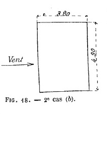
b. In the second case, the wind meets the statue from the side : the affected area of the statue and consequently also the bending moment Mb at the base are about 2/3 of the values found in the first case ; we shall have:
Maximum bending moment : Mb = 1 480 000 x 2 / 3 = 980 000 Kg
Effort in a rafter : Pb = 980 000 / (2 x 3.8) = 130 000 Kg
c. The wind strikes obliquely the exposed surface, which can be considered equal to the 5 / 6th of that face. So we have:
Maximum bending moment : Mc = 1 480 000 x 5 / 6 = 1 233 000 Kg
Effort in a rafter : Pc = 1 233 000 / 6.2 = 200 000 Kg
It is in this case the effort is maximum in a rafter. Note that, in the side opposite to the wind, the forces due to the wind loads and in addition, while in that directly hit by the wind, they are subtracted from one another.
The maximum compressive stress in a rafter is obtained by adding the maximum effort found previously for loads and wind. Its value is :
Tc = 200 000 Kg + 50 000 Kg = 250 000 Kg
The maximum tensile stress is set to the difference of the same quantities:
Tc = 200 000Kg - 50 000Kg = 150 000 Kg
The section of a roof beam is constant over the entire height; it is composed as follows :
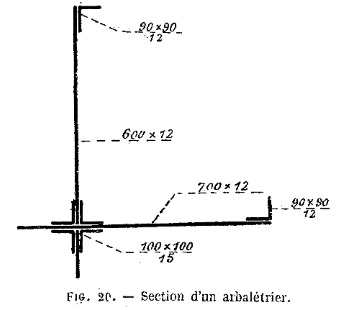
- 1 soul 700 x 12 8400mm2
- 1 soul 600 x 12 7200mm2
- 4 angles 100 x 100 x 15 11 100mm2
- 2 angles 90 x 90 x 12 4032mm2
Total sectional area : 30 732mm2
Maximum working coefficients will be:
- Compressive : R = 250 000 / 30732 = 8.1Kg par mm2
- Strenght : R = 150 000 / 30732 = 4.8Kg par mm2
Lattice Calculation
The lattice bars have to resist shear forces; they have the same composition in all four sides; the maximum efforts will be given for the case where the wind hits the statue face. Here is how one determines: We draw on the sketch the curve shear forces obtained by adding, for each point, all the forces that act over this. It then projects these efforts in the direction of the bars and a second curve is obtained giving the forces in the bars. Finally, on the forces to which the bars are able to withstand working at 6Kg, the line is obtained by steps of the purified, limited effort. The sketch shows that at any point of the lattice bar section is sufficient.
Polygon of forces
Polygon of forces
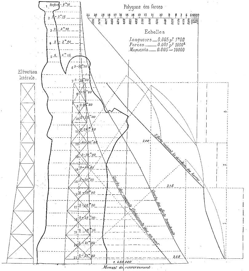
Reproduction of the polygon plan of the forces of Statue of Liberty
The following table summarizes: The number of bars, the total effort in the bars, the effort of a bar, the section of each bar in mm2, work coefficient per mm2
| N° | total effort | Effort | Section | Coefficient |
| 1 | 114 000 | 28 500 | 5208 | 5.47 Kg |
| 2 | 98 500 | 24 625 | 4512 | 5.50 Kg |
| 3 | 75 000 | 18 750 | 4032 | 4.65 Kg |
Calculation of moorings
The fastening rods of the frame in the masonry have to withstand a tensile force equal to that which develops in the lower part of a rafter, 150 000 kg. Each rafter is moored by three 120mm diameter rods 11 and 310 mm section. The working coefficient of these ties will be:
R = 150 000 / (3 x 11 310) = 4.4Kg / mm2
The masonry cube that will be interested in the ties of each rafters will, counting masonry to 2500 kg per cubic meter, of:
150 000 / 2 500 = 60 m2
Calculation of the right arm strength
The calculation of the force arm cantilever is more delicate. Its metal frame consists of four struts, the broken line, connected together by horizontal cross members and by diagonal angles. The horizontal cross divide the frame sections whose bases are rectangles with sides parallel to each other and also parallel to the faces of the main cell. The outer sides of each section have the shape of a trapezium, one of the diagonals is occupied by a brace. This framework focuses on the right side of the main battery, six-point crossbowmen of this face. Its height is 18m77, measured from the lower attachment to the upper level. She may have to bear, like the rest of the building, two different kinds of efforts:
- The weight
- The effort
The arm was decomposed for each of the calculations in 12 elements; the center of gravity of each of them, ie the application point of the force acting on these elements, was assumed to be situated on the axis of the metal frame. The following table summarizes this calculation, still assuming an equal effort wind 270kg.
The resultant of the external forces at any cross section of the arm, may have been determined by means of two funicular polygons, easy to construct, each of which gives a coordinate of the point of application of the resultant. The distribution of forces in the various bars of the framework was made following a graphical method of decomposition of forces. This breakdown was made in three planes of projection, to obtain for each bar three components of the force acting in her direction.

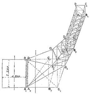
The backbone of the arm
The backbone of the arm
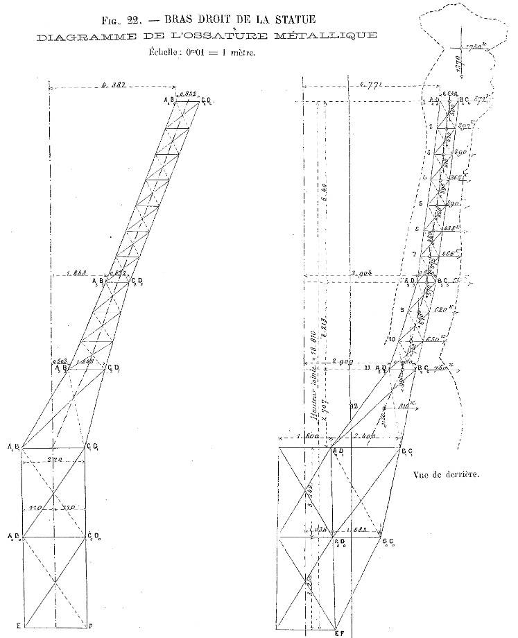
Replica of the backbone of the arm
The backbone of the arm
The backbone of the arm
Replica of the backbone of the arm
It was enough to ensure the stability of the construction, to seek the forces acting:
1 : Within six bars cut with a close-up of the plan A3 B3 C3 D3 (upper level)
2 : Within six bars cut with a close-up of the plane A1 B1 C1 D1 (lower level)
The graphical determination efforts led to adopt the following dimensions:
The rafters of the framework have, between attachment points on the main stack and the plane A2 B2 C2 D2, a section formed by two angles of 100 x 100 x 15 and 100 x sole 10. The surface this section is 6550 mm2. Between planes A2 B2 C2 D2 A3 B3 C3 D3 and the section is formed by two angles of 100 × 100 × 15; the surface is 5 550mm2 Above the plane A3 B3 C3 D3 to the item 5, by two angles of 100 x 100 x 12 whose surface is 4 512mm2. Since the element 5 to the top (level A4 B4 C4 D4) by an angle of 100 x 100 x 10 whose surface is 2 256mm2. We will check by an analytical method the dimensions of the two rafters. For this purpose we will assume the wind acting parallel to the vertical projection of the arm.
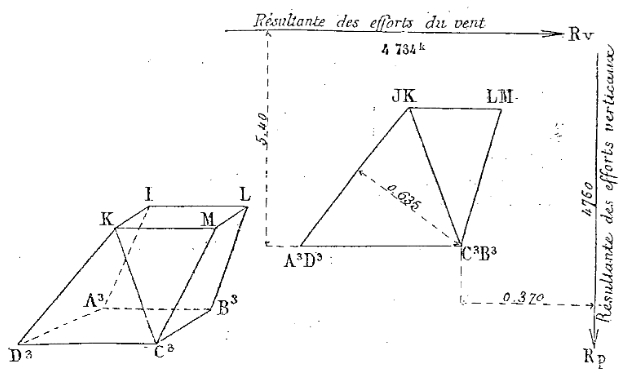
Consider a section of the arm between the element 7 and the element 8, ie above the plane A3 B3 C3 D3. The sum of the dead loads of items 0-7 is equal to 4760 Kg. The sum of the wind forces acting on the same elements is 4764 Kg. Let us determine the force in the rafter D3K. For this take the static moments of the external forces from the point C3: The moment of the force acting in D3K X must be equal to the sum of other times. So we have:
X x 0.635 = Rp x 0.370 + Rv x 5.40
Now, for one side, it can be assumed Rp = 1/2 x 4760 = 2380 Kg et Rv = 1/2 x 4764 = 2382 Kg
Where:
X = 21 500
This force is in the vertical plane and to have it in the direction of the rafter, we multiply by the 10/9, report of the actual length of D3K to the length of its projection. The force acting in D3K will be:
21500 x 10 / 9 = 24 000
Per square millimeter of the admitted section:
R = 24 000 / 4512 = 5,3Kg
Graphs decomposition for a wind direction perpendicular to B3 D3, gave the other two rafters:
In A3I a effort of 31 090 Kg
In C3M a effort of 33 470 Kg
Which gives for these two rafters, per square millimeter section:
In A3I a effort R = 6.85 Kg
In C3M a effort R = 7.40 Kg
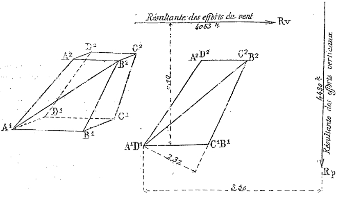
Consider now a section of the arm between A1 and A2 B1 B2 C1 C2 D1 D2: The external force due to the own weight is 8860 Kg, effort wind is 8106 Kg We will determine the force in the rafter as B1B2. previously, taking moments about A1. We have:
X x 2.32 = Rp x 3.50 + Rv x 8.10
Considering Rp = 4430 Kg and Rv = 4053 Kg, we find:
In the vertical plan, X = 21 000 Kg and in the B1 B2 direction : 21000 x 3.76/2.75 = 29 000 Kg.
Either for work coefficient : R = 29 000 / 6550 = 4.5 Kg
From the above discussion it follows that the sections of rafters do not work to a higher coefficient 8Kg. Moreover, in those sections of horizontal and diagonal bars, the coefficient is less than this limit. In summary, this iron framework may be regarded as established in the best strength and stability.
See as well: History of the statue of Liberty
Construction of the pedestal
The base was built between 1883 and 1886 on Bedloe Island, New York. It is a gigantic project led by architect Morris Hunt and the civil engineer Stone. The explanation of the base, its description and its history, especially that of construction, are explained here.