
Aerodynamics has undoubtedly been one of the main interests of the Eiffel Tower. With broadcasting it is the area where the greatest progress has been made. The installation of a laboratory on the 2nd floor allowed the study of the air resistance of the materials, from which we deduced the mechanical properties used nowadays in aeronautics.
A very small number of experiments were made until the nineteenth century on the fall of bodies taking into account the resistance that the air opposes their movement. However, apart from the scientific interest that it presents, the study of this question would make it possible to solve a great number of difficulties which are met at every moment in various practical applications, resistance of the air to the trains of railroads. and ships on the move, direction of balloons, aviation issues, influence of wind on buildings, use of wind as a motor, etc.
Until the end of the nineteenth century, the experiments made on this subject were executed mainly by printing to the bodies a rotation movement obtained with the help of a kind of carousel. According to the authors themselves, the methods employed give only incomplete results because of the entrainment of the air, the centrifugal force, and so on. In addition, the speed that can be achieved is very limited. We thought that the Eiffel Tower offered particularly advantageous conditions to study more completely this interesting question and to directly approach the study of rectilinear motion.
Principle of the method
When a body moves in the air, it experiences from it a resistance that increases with the speed of movement. Let us suppose that this body is solicited by a constant force, as it is, for example, by its own weight, when it is abandoned in free fall. If, instead of being plunged into the air, he was in a vacuum, his speed, initially zero, would constantly increase and his movement would accelerate indefinitely. If he is in the air, it will not be the same. As the speed of the mobile increases, it will experience a growing resistance, so that its movement will cease to accelerate and become uniform precisely when the resistance of the air will exactly balance the effect of gravity on the body.
If we measure, on the one hand, the speed V of the body at the moment when its movement becomes uniform, and on the other hand its weight P, we will know that the force exerted by the air on the animated body of the velocity V is precisely P.
By increasing the weight of the body, without modifying its surface, by the addition of a suitable weight, the velocity V of the limit uniform movement will be increased at the same time, so that the comparison of the various values of P with the corresponding thieves of V will reveal the law of variation of resistance as a function of speed.
To put this method into practice, the apparatus employed is based on the following principle:
Imagine a long thin wire subdivided into equal sections, for example 20 m. Let the subdivisions of consecutive sections be slightly attached to the suspension points, leaving the different successive sections of 20 m between them. Suppose at the suspension points there are electrical contacts capable of operating under the influence of a very slight traction of the wire and joined to a stylus pen adapted to a rotating cylinder according to the well-known arrangement. Let's drop the heavy body at the free end of the wire.
The moment of departure will be recorded on the cylinder by the first contact. As soon as the body, when falling, will have traveled 20 m, it will have carried with it the first stretch of wire that will have developed vertically following the body; the second contact will work in turn, and so on. If a registering tuning fork is added to the cylinder, for example, 100 vibrations per second, the graph plotted on the cylinder will indicate, in hundredths of a second, after which time intervals the body has traveled 20, 40, 60 m . As soon as the motion becomes uniform, we will see on the graph that successive contacts will operate at equidistant time intervals. These intervals being measured in hundredths of a second, by the sinuosities of the curve of the tuning fork, we will immediately have the uniform velocity of the mobile.
Practical arrangement of the device
Here is a description of the fall device, description made by Gustave Eiffel himself.
The apparatus bearing the test plate fell in free fall, and guided by a vertical cable of a length of 115 meters, giving speeds of up to 40 meters per second. It consists essentially of a heavy mass pushing the plate in front of it, through two calibrated springs. Their action is antagonistic to the resistance of the air, so that the displacement, relative to the rest of the apparatus, of the movable part carrying the surface makes it possible to evaluate the tension of the springs, from which one deduces the resistance itself. For this purpose, a tuning fork with 100 vibrations per second, set in motion at the beginning of the fall and secured to the moving part, is provided with a stylet which can move along a generator of a vertical cylinder carried by the frame of the device. This cylinder, covered with a paper blackened with smoke, rotates with a speed proportional to the speed of fall, thanks to a roller provided with fine serrations which rolls along the cable on which it is energetically pressed. At the same time, the vibrations of the tuning fork inscribe on the cylinder the time elapsed since the origin of the fall. As, on the other hand, the abscissae are proportional to the spaces traversed in the fall, the diagram furnishes, by one and the same curve and at any moment of the fall, the three quantities which interest us: the force, by the measurement of the ordinates representing the tension of the springs, the space traversed, by the reading of the abscissae and finally the time, by the counting of the vibrations, from which one deduces at every moment the speed and the resistance.
In practice, it would be impossible to leave floating in space the successive sections of the wire, which by the effect of air currents intertwined with each other. This disadvantage has been avoided by the following artifice.
Each section of the wire is wound on a wooden cone C1, C2, C3 (see Fig. 220) fixed vertically, the tip turned downwards. It is easy to see that the thread dragged by the fall of the mobile follows it with the greatest ease; because of their conical shape, these coils, although immobile, allowing this thread to unfold, so to speak, without friction. We have also evaluated by a direct measurement, as will be seen later, the delay that can come from a resistance to unwinding the wire.
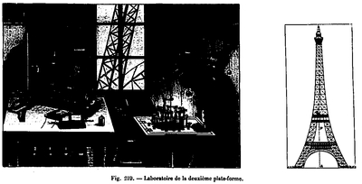
The laboratory of the 2nd floor of the Eiffel Tower
The laboratory of the 2nd floor of the Eiffel Tower
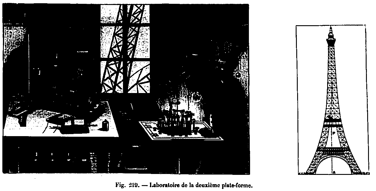
The laboratory of the 2nd floor of the Eiffel Tower
The electrical contacts intended to record each 20 m path are formed of two metal blades LL 'insulated in 1 by a piece of ebonite and whose ends are touching via platinum contacts. This kind of clamp is crossed by an electric current that will animate the pen of the recorder and is interrupted when the two branches apart. By passing from a cone C1, C2 to the next it is engaged in the free interval that leave between them the two branches of each clamp, immediately above the platinum contact. When the cone C is unrolled, the wire fixed to the moving part for a moment spreads the branches of the clamp and opens the current which is restored immediately. It is then that the pen of the recorder leaves a mark on the rotating cylinder. Then cone C2, unfolds in turn; the second clamp opens after a new course of 20 m, and so on. The blades LL 'which constitute each clamp being very flexible, the resistance they oppose to the spacing by the passage of the wire is extremely low. In tests made to evaluate this resistance, a weight of 2 g falling from the height of 10 cm was enough to remove these blades. A very simple calculation makes it possible to ensure that this effort would delay by less than 1 mm the fall of a weight of 1 kg after a course of 20 m.
To evaluate the double resistance that can come from the unwinding of the wire, its friction in the air and other passive resistances, several methods have been used:
1. A cylindrical arrow of weighted wood has been dropped at its upper part by a metallic mass terminating in a tapered point. Because of its small section and its elongated shape, this arrow must itself experience only a small resistance from the air. It must, therefore, take a movement of fall little different from that which it would have in a vacuum. This last conclusion is still applicable, if the possible resistances due to the driven wire are negligible. Now, in several very concordant experiments, it has been found that the total duration of the fall of this arrow does not differ from that of the theoretical fall in the vacuum of more than 20 / 1000th of its value.

Diagram of the apparatus for measuring the fall of the bodies
Diagram of the apparatus for measuring the fall of the bodies
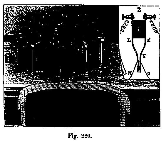
Diagram of the apparatus for measuring the fall of the bodies
2. A second means of verification consisted in dropping the mobile completely free and not attached to the wire. The moment of his departure is recorded by the electric pen whose circuit is interrupted by the very fall of the body at the moment when it starts moving. Arriving on the ground, this mobile hit a wooden panel supported by springs and through a current that animates the pen of the recorder. At the moment of the shock, the panel gives way and the current is interrupted, so that the precise moment of the arrival is recorded as well as that of the departure. By comparing the total time of freefall thus obtained with that given by the same mobile attached to the wire and making the tongs work, the difference in these durations represents the sum of the delays experienced by this mobile from the passive resistances due to the apparatus. In two consecutive experiments made with a copper cylinder weighing 2080 g, it has been found that the difference in the fall times of this cylinder, when it is attached to the wire and when it is entirely free, is 0, 04 second a tolal duration of fall of 5 seconds. The delay due to the driving of the wire is therefore less than 1%.
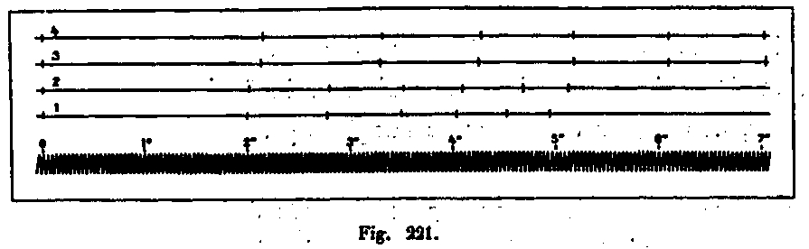
The apparatus made it possible to verify that the resistance opposed by the air to planes of equal surface, moving in a direction normal to these planes, is independent of their shape. For circular, square, and triangular surfaces, equal fall times have been found, as can be seen in Figure 321, lines 3 and 4. This figure is the quarter-point reduction of the actual graphs. The curve of the tuning fork is plotted assuming that it performs 25 vibrations per second.
It has also been verified that the resistance experienced by a plane operating in the air is proportional to its surface. Two square planes whose surfaces were between them like 1 and 2 were weighted by weights that were in the same ratio. The duration of fall was 6.92 seconds and 6.96 seconds respectively, approximately the same number and according to which proportionality must be accepted.
The most numerous experiments have focused on the evaluation in kilograms, per square meter, of the resistance opposed by the air to a moving flat surface and on the search for the law of variation of this resistance as a function of the speed. We have seen above how we can obtain this law by evaluating the weight of the mobile and by measuring its speed when its fall movement has become uniform. In all the experiments in question, the weight of the surfaces employed was adjusted so as to obtain the uniformity of the movement after a course of between 60 and 100 m.
We know that it is generally accepted that the resistance of the air is proportional to the surface and square of the speed of the moving body, at least for moderate speeds such as those referred to here. The formula expressing this law is: P = R S V2.
P being the pressure of the air on the body, S its surface, and V its velocity. Engineers generally adopt a value of R = 0.12248, where P is expressed in kilograms per square meter, S in square meters, and V in meters per second. If this formula is correct, the value of R calculated according to it, using a series of corresponding values of P and V, for planes of the same surface S, must always be the same for speeds different. The experiments carried out at the Eiffel Tower have given for the values of R thus calculated numbers quite close to each other so that it is necessary to admit the accuracy of the formula from the practical point of view for speeds up to at 25 m per second.
But the numerical value of R thus obtained is very different from that adopted so far. The various values found for R oscillate between 0.069 and 0.071. The average value to be admitted is therefore 0.070.
The determination of this coefficient, whose value 0.07 is very different from the number 0.125 admitted by the standard formulas and which reduces the wind pressure to 57% of that which was generally adopted, was also the subject of research by Mr Langley (Experiments in Aerodynamics) and reported in the Proceedings of the Society of Physics (March 1892). These experiments were made using a carousel of 9 m radius at the end of which was fixed a flail mobile in all directions around its center, by means of a Cardan suspension and to measure in size and in the direction of pressure acting on a plane. This plane itself could, in the sense of its length, be placed in a direction parallel or oblique to the direction of the movement. For a square plan of 505 mm side and velocities varying between 5 m and 11 m, the previous general formula was verified. This formula is for normal planes very little different from that found by MM. Cailletet and Colardeau, which gives a little stronger results.
Evolution of the device
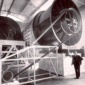
Gustave Eiffel Wind Tunnel
Gustave Eiffel Wind Tunnel

The Gustave Eiffel wind tunnel, today in Auteuil
Unfortunately this lab was not efficient enough, and the techniques improving it designed a blower to test the materials in conditions closer to reality. This wind tunnel allowed him to improve his knowledge of the properties of materials facing the wind. He performed more than 5,000 tests on the air resistance of wings and propellers, allowing aviation engineers to design the profiles of airplane wings that will be built in the years following the erection of the tower. The wind tunnel was in operation from August 1909 to December 1911. From 1912 it was moved to Auteuil, rue Boileau, the municipality of Paris judging the building unsightly. This new laboratory was equipped with two turbines (1 and 2 meters). That of 1m was dismantled in 1933, but the other ... is still in operation!
Conclusion
Regarding the fall of the bodies and the resistance of the air, the Eiffel Tower has been of great use. It was from the laboratory that Eiffel had installed on the second floor that Mr Louis Callet, a member of the Institute, and Mr R. Colbert, made some interesting experiments whose reports were delivered in "Les Proceedings of the Academy of Sciences "(1892) and" Nature "(July 9, 1892), then in" The Reports of the Society of Physics "of November 4, 1892. In the link below you have the account full report of these experiences, as it was written at the time.
See also: