
Study of the basement and choice of the final location
As a result of the numerous surveys carried out in the Champ-de-Mars, the bottom layer of this subsoil is formed by the powerful layer of plastic clay which generally prevails in the Paris basin: it is located at 14 m below the ground and has a thickness of about 16 m; below is the chalk. This clay is dry, compact enough, able to withstand pressures of 1 to 4 Kg per square centimeter, but it is however of insufficient strength to receive the direct load of the foundations of the Tower.
This layer of clay, slightly inclined from the Military School to the Seine, is surmounted by a sandbar and compact gravel, which is eminently fit to receive foundations.
Up to the edge of the balustrade between the state-owned Champ de Mars proper and the square at the front, which belongs to the City, that is to say, about the height of University Street, this layer of sand and gravel has an almost constant height of 6 to 7 m, and solid foundations can, in this part of the Champ-de-Mars, be established dry without any difficulty, as well as this took place for the various palaces of the Exhibition.
Beyond that, we enter the old bed of the Seine, and the action of the waters has reduced the thickness of this layer, which is always decreasing, to become almost zero when we reach the current bed. This is shown in Figures 1 and 2 of the board II.
If one looks at the plan of Paris, drawn up by Roussel in 1730, one can get an idea of what was formerly the shape of the bed of the Seine. The current bed, with rectification of encashment near, is very clearly traced. But there was a second arm whose bank was almost an extension of University Street. He spared a little island, called "Island of the Swans," which was used for wooden works; behind were the vegetable swamps of Gros-Caillou, in which the Ecole Militaire was later to be built. This arm was, moreover, rapidly being silted up: the plan of Berniquet (1789) still indicates it, but rather as a ditch; the construction of the Iena bridge was to complete its disappearance by a final backfilling.
The location has been confirmed in the foundation of piles 1 and 4, which occupy approximately the exact bed and are located 120 m behind the current wharf. Also in these points one finds, in a layer of mud or clay more or less sandy, debris and detritus of any nature, wood, fragments of pottery, bones of domestic animals, and even a masonry formed by superimposed blocks which must belong to a quay wall. All this neighboring part of the Seine is quite unfit to receive from foundations made by ordinary methods, such as those which can be established in the more remote parts of the Champ-de-Mars. But administrative considerations did not allow the establishment of the Tower in the domain of the State, which would have resulted in long formalities to legalize an alienation lasting longer than that of the Exhibition. They were avoided by placing the Tower in the square, which was the domain of the City, and obtaining for this purpose the authorization of the Municipal Council. The latter, in return, asked that at the expiration of the concession, the Tower become the property of the City.
As for his position even in the square, we had no choice. Certain preferences existed to place the Tower on the quay itself, so as to distance it as much as possible from the buildings of the Exhibition and to reduce the appearance inconveniences that were feared for them from this neighborhood. But it soon became clear that around the wharf, the layer of sand and gravel disappearing completely, the foundation became almost impossible. It was therefore decided to remove it from the Seine as far as the boundaries of the square permitted.
The two rear batteries were thus straddling the separating balustrade on easy terrain, and the two piles in front could come to be based on the sand and gravel bench, which at that point was still above the ground. clay, a thickness of 3.50 m, which offered complete security.
Stack Foundation 2
The two rear stacks, which bear the numbers 2 and 3, are placed, as we have just said, near the old balustrade, 216 m behind the wall of the wharf. The natural ground is at this point at the +34, the supply lands of all kinds and the inconsistent embankments of which it is formed have a thickness of 7 m. We meet at the + 27, which is the normal level of the Seine (dam of Suresnes dam), the layer of sand and gravel whose thickness at this point is about 6 m. It was therefore possible, without exhaustion, to obtain for these two piles a perfect foundation.
The works were inaugurated, on January 28, 1887, by the beginning of the excavations of the pile 2 (board II, Fig. 4, 5 and 6). A general search was made up to Hill + 29 according to the usual methods used for excavations of Parisian buildings, that is to say with the aid of dumpers accessing the bottom of the excavation by properly arranged ramps, coming from take charge of a wide front and transport the excavation to public landfills.
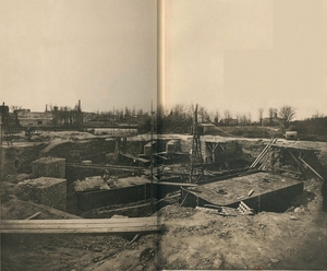
Foundations of the Eiffel Tower
Foundations of the Eiffel Tower
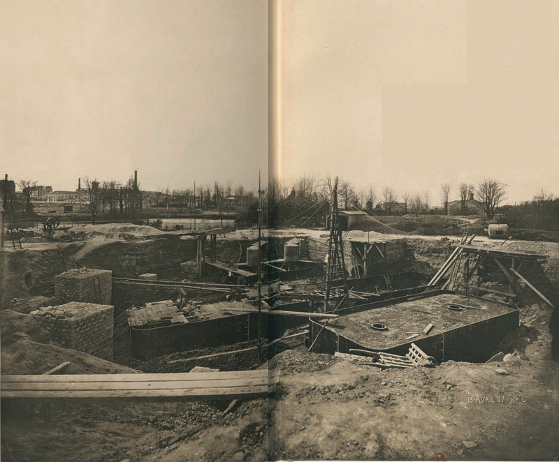
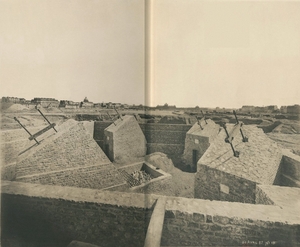
Foundations of the Eiffel Tower, photo taken April 13, 1887
Photos reproduced with the kind permission of L'Illustration.com.
This work, which included the 5 351 m3 off-road, was completed on February 23 and proceeded with great activity under the direction of MM. Aubry and Huguet, entrepreneurs. On certain days, 350 dumpers with two horses carrying 2.50 m3 were loaded, and 40 dumpers were loaded onto a horse carrying 1.50 m3.
Then, while feasting the lands on the platform of the general excavation, the excavation was made for the foundation of the four massive masonry supporting each of the rafters. These excavations were given a depth of 2.00 m which made it possible to reach the solid layer of gravel at water level (+ 27.10). These excavations, which were to be filled with concrete, had, for three of the massifs, 10 m by 6; the fourth, of special shape, which was to receive the elevator paths, was 14 m by 7.40 m. Their cube was 492 m.
Each pile was surrounded by walls serving as a foundation for the masonry bedrock, which constituted the apparent base of each. These walls were built on vaults which rested either on the massifs themselves, or on separate pillars founded on the layer of gravel. These excavations had a cube of 90.50 m3.
Finally we decided, to facilitate the loss of atmospheric electricity in the ground, to have 3 m under the platform, that is to say 1 m below the level of the Seine, two long cast iron pipes about 20m long and 0.50m in diameter, arranged between the massifs. One of their extremities had to curl vertically and emerge at the level of the natural ground to be connected by metallic conductors to the irons of the Tower. These excavations, which included dredging and shoring, were 1 m at the base and 3 m deep. Their cube was 144 m3. After the placement of the conductive pipes, they were backfilled.
The excavations of the massifs and the walls being finished, one proceeded to their filling by hydraulic concrete formed by 1 m3 of rolled pebbles and 0,5 m3 of mortar. This one itself consisted of 1 m3 of river sand and 250 kg of Boulogne cement (Famchon mark). The mortar was manufactured by mechanical grinders and cast in place by vertical cross-link mixers. The concrete cube used was 582 m.
Once the concrete had been leveled at + 29, it was surmounted by the upper masonry.
The massifs under the crossbowmen were in the shape of a quadrangular truncated pyramid whose axis was directed according to the oblique inclination of the crossbowmen, or rather was such that the curve of the pressures came to approximately cut in their middle the plans of the bases . These seats themselves were horizontal in the lower part, and normal to the pressure curve in the upper part to prevent slippage. The connection was made by fan-shaped seating. The anterior and lateral faces were arranged vertically with redans, the posterior side was inclined. Figure 1 of the board IV indicates these provisions. The maximum height was 7.50 m and the width at the base of 5.00 m.
These massifs consisted of rubble quarries Souppes, laid in hydraulic mortar at a rate of 250 kg of Boulogne cement per cubic meter of sand.
All this masonry, into which only the highest quality materials have been brought in, has been made with extreme care, so that, even if it were immediately loaded after its establishment, it gave rise to no settlement; it is for this reason, moreover, that the use of lime, whose setting in the middle of the large masses is uncertain as duration, has been discarded. We only used this one for the perimeter walls, which could without any inconvenience be constructed, according to the use, with mortar of lime.
The massif in front of the center side had a somewhat special shape, indicated by Figure 1, to receive the elevator cages.
The inclined face which limits the upper part of each massif received the support stones, composed of two hexagonal bases each having a thickness of 0.50 m and a width of 4.00 m for the first and 3.00 m for the second. These stones came from the best quarries in Château-Landon and their resistance to crushing is, according to the experiments we asked the École des ponts et chaussées and the Conservatoire des Arts et Métiers, of 1,235 kg on average by cm2. It is these stones that receive the cast iron shoes on which come the rafters.
In the center of each of these massifs, are drowned two large anchor bolts 7.80 m long and 0.10 m in diameter which, by means of cast iron shoes and double T irons, are of interest. most of the masonry of the massifs.
This anchorage, which is not necessary for the stability of the Tower, which is ensured by its own weight, however gives an excess of security against any overturning and should be, moreover, used during the cantilevering of the pillars in iron. These bolts are not simply drowned in masonry, where their position would have been invariable. They are housed in a cast iron pipe inside which they can have a small displacement. Indeed, whatever the care with which one had to proceed to the placement of the bolts which were to fix the support shoes, a little game was necessary to obtain the rigorous position, envisaged with the drawings, of the metallic part.
The three lateral massifs each cubed 196.50 m3; that of the elevators 358.68 m3, together 948.15 m3. Each of the 9.845 m3 cubic stone crowns, or 39.38 m3 for the four.
The perimeter walls (board V, Figs 3 and 4) of 0.75 m d The thickness was established in hydraulic lime masonry at Echoisy, on pillars joined by arches of 5.55 m of rope, and 1.00 m of arrow. They were leveled at +35, the final ground level of the Champ-de-Mars. Their cube is 316 m3.
When all was finished, the masonry was drowned in an embankment brought to the ground level. The cube of this embankment is 4,170 m3.
Masonry was started on March 4th and ended on April 10th. The number of men working there averaged 47, including 20 masons and 27 laborers.
Stack Foundation 3
The excavation of this pile was made differently from that of the pile 2. The cuttings were no longer to be transported to landfills, but to be supplied in the central part of the Tower, in order to raise the level of the Champ-de-Mars , which formed a depression in this place, to fill the voids around the masonry beds. They were transported by horse-drawn wagons and rolling on two lanes which brought them to the desired points. (board III, fig. i).
The excavation, which had the same dimensions as the previous one, was dug to the same depth, at + 29.00.
It was started a few days after the first, on the 29th of January, and ended on the 8th of March, at the end of thirty-nine days, a little longer than the first, because we had much less powerful attacks than 'with the many dumpers that presented themselves to the loading. The cube of this excavation was 5,498 m3.
The small excavations for the concrete of the massifs, that of the perimeter walls and for the laying of the conduits of electricity were made from the 1st to the 12th of March; their cube was 741 m3
The masonry was similar to the first with regard to the massifs; the perimeter walls were the only ones different. In fact, the interior of this pile had to remain empty to receive the mechanical service of the Tower, as generators, machines, pumps, dynamos for lighting, etc.
These perimeter walls (board III, fig 4; board IV, figs 13 and 14; board V, Figs 5 and 6) have 1.50 m at the base and 0.75 m at the top. They connect to the massifs and rest on concrete pillars by arches of 5.00 m and 3.36 m placed in the lower part, from where they rise full on a height of 6m.
Backfilling was done behind the mountains and walls. The ground itself, which was to be that of the engine room, was raised up to +30,50.
These foundations were started on March 9 and ended in late April.
Wells for sounding piles 1 and 4
For the exact recognition of the difficult ground upon which the water-stacks of Nos. 1 and 4 were to be founded, we had first made use of ordinary sounding methods, carried out by MM. Paulin and Arrault. But their results, full of uncertainty, did not give us complete satisfaction.
Foundations of the Eiffel tower
Foundations of the Eiffel tower

Foundations of the Eiffel Tower, photo taken 20 avril 1887
Photos reproduced with the kind permission of L'Illustration.com.
What conclusions from the point of view of the establishment of a foundation can reasonably be based on the examination of a few cubic decimetres of cuttings, most often diluted by the waters to which the borehole itself gave access and brought back to the day by the poll spoon? What is the consistency of this ground in its natural state, and what charge can it be made to bear? The results of the survey give no indication in this respect and are the cause in the work of frequent errors having the most serious consequences.
As it was of great interest, for the organization of the work and the preparation of the rises, to know in advance not only the depth of the soil layer where one had to stop, but also the exact nature from the basement, we did not hesitate to make for each of these piles wells with compressed air intended to inform us in a complete way either on the thickness of the layers, or on their consistency.
We were perhaps the first to use this mode of research, which gave us the best results and which is basically very inexpensive, when we have compressed air equipment, that is to say an airlock and a blowing machine.
Our wells consisted of a sheet metal tube 2.00 m in diameter and 3 mm thick. In the lower part is arranged the working chamber surmounted by the chimney, at the top of which is installed the airlock. The annular void space above the ceiling of the chamber serves as a store for the counterweight intended to balance the pressure. This counterweight can be constituted either by irons or by pebble or concrete, as we have done to these wells. We had to leave them in place to make them the conductors of the atmospheric electricity, by connecting them to the irons of the Tower.
As the general search of the pile was not complete, we placed this cylinder out of the pile and pushed it down from the natural ground. The usual processes of the wells were first used until the water was stopped, at a height of +27,00, at 7,43 m below the natural ground (+ 34, 53). The airlock and its chimneys were then installed and we descended in 7 days of 7.07 m giving a total descent of 14.50 m. We were then in the chlorite limestone and, as we had some difficulty in loading the tube sufficiently to lower it, we made an additional survey with the auger of 1.40 m to recognize the clay, whose very clear presence was indicated at + 18.63 (see figure 3, board II).
In the meantime, there had been a layer of 7.49 m of fill, sandy clays and fine sand to a depth of 5.99 m and finally a layer of sand and compact gravel excellent for foundations at + 22, separated from the clay, either by the layer itself or by chlorite limestone, to a thickness of 3.37m. It was therefore easy to sit on this couch.
For pile 4, the general excavation was already carried out and the sampling well could be established in the center of the four caissons by beginning the driving operations at +28. The natural soil was at + 34.60.
The penetration was pushed this time to a penetration of 1.75m in the plastic clay, which was clearly recognized the nature and compactness, which was quite large: this clay was dry, very strong and could already by itself even support loads of 3 to 4 kg at least per square centimeter. Clay sands and sand-blasted vases had been encountered at a height of 6.00 m, followed by a good layer of sand and gravel at +22, separated from the clay by a thickness of 3.15 m of gravel and limestone. chlorite and ferruginous sandstone. This layer could therefore, with full security, receive the foundations, the charge per square centimeter of which did not exceed 4.9 kg, as is apparent from the foregoing calculations.
We have thus been able, by this very sure mode, that we can not recommend too much, will determine the advance in an absolute manner the organization of our work, our supplies as rises, masonry materials, etc.
The box can be largely removed for use again. In the present case, we left it in place, removing only the chimneys. They have been replaced by a cast iron vertical pipe projecting outward and plunging widely into the water. The voids were filled with pebbles; so we had an electric conductor leaving nothing to be desired.
Given this low height of 5.00 m to go under water, one may wonder if there would have been, from the point of view of expenditure, advantage to use for these two piles a different mode of that of compressed air and proceed by dredging in an enclosure with submerged concrete.
Doubt is hardly possible: for, in spite of the soundings, we were not, in this part so tormented with the ground of the Champ-de-Mars, sufficiently sure of the ground for all the surface included in the feet. It was therefore necessary, in these circumstances, to adopt a solution that meets all the contingencies. Moreover, the use of compressed air has such advantages, either as safety in the work or as certainty in the result obtained, because of the immense interest that one had to walk as quickly as possible in getting rid of all hazards at once, and in establishing foundations which give absolutely no fear for the future, we have not hesitated to employ this method, although it was noticeably more expensive than any other. This choice was moreover fully justified by the following, as we encountered in the caissons of the pile 1 considerable remains of masonry and tree trunks which would have been a very serious obstacle to the prompt execution of the work by d. other processes.
Stack Foundation 4
We began, as for the other piles, to establish a general excavation of 6.00m of depth at the + 28,00 scale. The natural terrain was + 33.92 (seeboard II, fig. 12 et 13).
The upper part of this excavation, to a depth of approximately 4.00 m, was removed from the dumper to be transported to public landfills, following the method used in stack 2. 4748 m3. For the remaining 2.00m, of which the excavation was to be deposited in the central part of the Tower, we made a basin descending to the coast + 28.00 and crossing the excavation. It was connected to a ramp on which was laid a way, and at the end of which was arranged an inclined cable hoist, moved by a locomobile. The wagons came to load along the bowl and poured on both sides of the way of deposit (board III, Fig. i). This method removed 2,421 m3.
Map of excavations of the pile 4
Map of excavations of the pile 4

Map of excavations of the pile 4
Map of excavations of the pile 4
Map of excavations of the pile 4
Map of excavations of the pile 4
This last mode of work was not very expeditious, so the search, begun in the first days of February, was not finished until the 25th of March; it consisted of 7,169 m3.
At the site of the caissons and up to the level of the water, the excavations necessary to accommodate them were made; they had a surface of 15 m by 6 m.
On the 26th of March the assembly of these caissons began; their length was 15.24 m and their width was 6.00 m with rounded corners (the first one was only 14.24m long, but we thought it would be better to lengthen all the others by 1.00m).
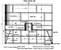
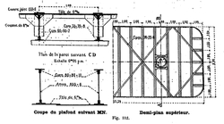
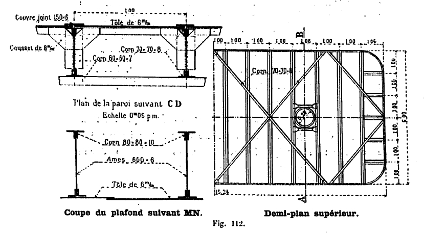
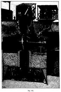
The height of the working chamber measured from the cutting edge to the ceiling was 1.80m (see Fig. 112). The vertical walls exceeded the ceiling of 1.20 m, which gave them a height of 3.00 m; they were stiff from meter to meter by consoles-struts in angles, having 0,80m at the top.
All the joints were vertical; they were located at the right of the consoles and covered by covers. The whole wall was delivered to the construction site divided into eight sections, each of which had its internal consoles completely riveted in advance: those on the long sides were not less than 7.00m in length.
The wall plates were 6 mm thick, they were stiffened at their lower part by a flat iron of 220 X 18 mm thick forming knife and a protruding angle of 100 x 100 forming support during the interval of the descents. The ceiling was formed by a sheet of 6 mm thick, stiff meter by meter by steel beams and angles of 0.60 m in height, which came to river on the consoles. Each of the sections of the ceiling carried two of these beams riveted in advance, the joint was made in the interval of two beams.
The entry lock
The entry lock
The entry lock
This division into sections was intended to minimize the number of rivets to be placed on site. The assembly was, moreover, very easy: one mounted on trestles the sections of ceiling, then one matait with jacks the sections of the opposite walls which came to be applied against the ceiling: one proceeded immediately to the riviere, The assembly a complete box, thus prepared in the workshop, lasted only two days.
Two of the sections of the ceiling bore circular apertures of 0.90 m in diameter on which the so-called chimneys of sheet metal, which supported the equilibrium chambers or airlock, fitted.
The rises, riveted as and when the caissons were sinking, were formed by sheets of 3 mm and 1 m in height.
Each box with its two rows of rises weighed 3,756 kg.
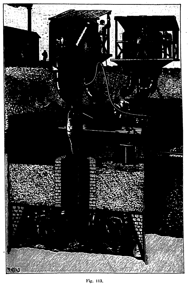
The airlock, of our usual type (Fig. 113), was 2.00 m in diameter and 2.00 m high. It consisted of a cylinder of sheet steel closed by two caps, the lower of which fitted on the chimney. He carried two horns forming locks and he was provided with a door for the exit of the workers. The excavations were mounted in sheet metal skips using a winch moved from outside by men installed in a light platform carried by the airlock.
The air pump, powered by a locomobile of 15 horses, was placed in a shed on the bank; the air arrived by rubber hoses coming to fit the lower part of the airlock. The general lighting of the building site was made during the night by arc lamps; the interior of the box was also lit by electricity.
Before sending compressed air, the interval of the consoles was filled with brick masonry; then all the ground that could be removed without being inconvenienced by the water was removed in the open air in the interior of the caisson with the help of a bucket winch and buckets. At last the chimneys and the air-chambers were assembled, and we proceeded as usual, according to the methods which are too well known for us to describe them here.
We will only say that the filling below the working chamber, as in the chamber itself, was made of cement concrete at 250 kg per cubic meter of sand.
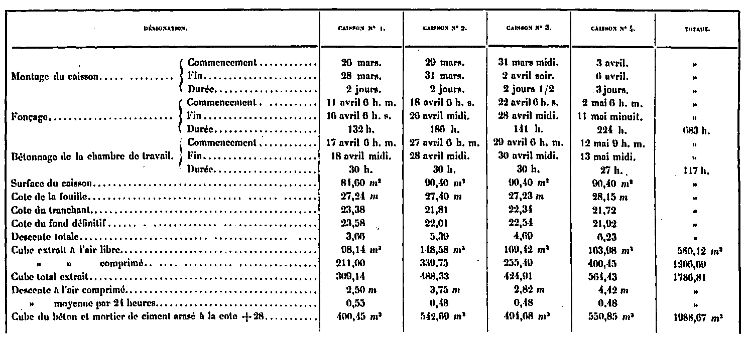
We summarize in the table below the data relating to this execution, as they result from the attachments:
Elements relating to the battery N ° 4
On the leveled concrete at +28, the masonry masts were raised to support the rafters. They were similar in shape and size to those in Stacks 1 and 3 except that, starting from +28 instead of + 29, they were one meter taller. For the three similar massifs, the width at the base was always 5.00 m, but the height at the highest point being 8.50 m, the length at the base was 9.61 m.
As for the central massif receiving the lift Combaluzier, instead of having 7.40 m as in the pile 2, it was able to keep the width of 6.00 m as the others and do not increase the width of the box; for this purpose the side walls were replaced by an iron frame with brick vaults 0.22 m thick. It is formed by vertical T irons 0.30 m high and 1.60 m apart. These irons are joined at their upper part by a sheet metal beam and brackets of 0.50 m height arranged horizontally. The shape of this solid mass, the void of which receives the elevator shaft, is given by figures 31 to 34 of the board IV.
As for the perimeter walls (board V, Fig. 7 to 10), they are established with arcades on pillars, whose masonry starts at the + 28, without concrete base.
The cube of each of the three similar massifs is 242.66 m3, ie for the three 727.98 m3.
That of the central massif is 374.42 m3, that of the brick filling of 23.51 m3. The weight of the frame iron is 4,238 kg.
The cube of the perimeter walls lined with hydraulic lime is 355,70m.
After completion of the masonry work, general backfilling was done by 4,218 m <3> of the land taken from the cuttings in storage.
All the work was completed on June 16, 1887.
Foundation of the pile 1
This foundation is similar to that of stack 4, and we will be, to avoid repetition, very brief about it.(See fig. 10 et 11 de la board II, fig. 1, 2, 5 of the III, fig. 9, à 12, 23 to 30 of the board IV).
The average grade of the ground being of approximately +34,00, the general search, leveled at the + 28,00 mark was finished on April 9th. The upper part, which was accessed by a ramp, was transported by dump trucks to public landfills. The cube was 3,081 m3
The lower part was put in deposit between the feet of the Tower; it has been raised to the necessary height by an inclined plane with double track installed in the ramp. At the top was a lift truck powered by horses. From there, moving tracks carried the wagons to the desired place. The cube thus transported was 3 953 m3.
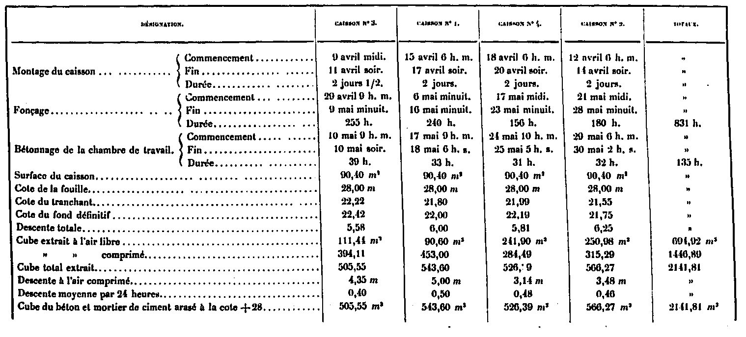
The caissons were similar to those of stack 4 and had an area of 15.24 m by 6.00 m; they were descended to the same average depth, that is to the coast +22. The sinking of the 1st caisson (No. 3) began on April 29th and the concreting of the last caisson (No. 2) was finished on May 30th. The sinking and concreting of the four caissons of this pile were made in the extremely short time of a month. No other process than that of compressed air would have allowed this work to be carried out so quickly and so surely.
we summarize in the table below the data relating to each of these boxes N° 3-1-4-2
The lateral massifs and the rear mass were similar to those of the pile 4. It was the same for the central massif, which was to receive the elevator Otis. The masonry of this pile was finished in the last days of June
All the foundations
The foregoing details provide all the necessary information about this important part of the work. It is not without interest to summarize them as a whole. The work, begun on January 26, 1887, was completed on the following June 30th. It was therefore executed in the relatively short time of 5 months. The excavations consisted of 30 973 m 3, breaking down as follows:
- Transported to public landfills: 13 272 m3
- Deposited between the feet of the Tower: 12 305 m3
- Stocked on the banks: 1 553 m3
- Extracts from caissons (including 1,900 in the open air): 3 813 m3
- Total: 30 973 m3
- Reversal of soil for backfilling piles amounted to 13 898 m3
This last figure seems excessive and can be criticized at first sight; it is questionable whether we should proceed, as we have done, with general excavations down to + - 29 for piles 2 and 3 and + 28 for piles 1 and 4, or if It would not have been more economical to make isolated excavations at the precise points where masonry was to be established. We do not believe that such criticism would be justified.
Indeed, leaving around the walls or pillars the necessary space to conveniently carry out the construction, one could not arrive at a cube less than 20 000 m3. This cube, compared to that of 31 000 m3 achieved gives a surplus of 11 000 m3.
These 11 000 m3 were paid: 1.40 francs per meter for excavation and 0.50 francs for backfilling, a total of 1.90 francs per cubic meter, which entails an expense 21,000 francs. However, we estimate that this additional expense is well compensated for by the speed and ease of the work either of the excavations or the masonry, as well as the absence of difficult and dangerous smears and finally by the added value that would have resulted in the assembly of the cuttings extracted from the wells. We believe, therefore, that the method employed was correct and that it should be recommended without hesitation in similar cases.
As for the masonry, they include:
- Cement stone masonry: 157 m3
- Souppe rubble masonry with cement mortar: 3 919 m3
- Concrete cement for ordinary bed foundations: 982 m3
- Concrete in the caissons: 4,130 m3
- Stone masonry with hydraulic lime mortar: 1,619 m3
- Lime concrete for foundation of walls: 1 639 m3
- Brick masonry: 47 m3
- Total: 12,493 m3
- In which he returned: 1,000 tons of cement and 210 tons of lime.
The work was carried out with great regularity, under the direction of Mr. Martin as head of department, Mr. Alalinarde as foreman-stonemason for masonry and Mr. Saint-Martin as foreman of the work of caissons.
See also: