
It was at the end of the construction of the tower that Gustave Eiffel had installed a free air pressure gauge for the measurement of high pressures. This was of great interest at the time: By its high accuracy, it had to be able to calibrate nitrogen or hydrogen manometers for laboratory experiments or industry. The description below was made by Mr Cailletet, of the Academy of Sciences, to whom Eiffel proposed this installation. So we see again the interest of the Eiffel Tower for science.
Arrangement
Open-air manometers are the only instruments that can practically, precisely and with a constant approximation, measure the pressures of gases or liquids. That's why I had installed, first on the inclination of a hill, then, later, at the artesian well of the Butte-aux-Cailles, a free air manometer of more than 100 m of height.
This arrangement has since been imitated by several physicists. But the difficulties of maneuvering and observing an instrument installed in these conditions always leave uncertainties about the accuracy of the results. The construction of the Eiffel Tower provided exceptional conditions for the establishment of a 300 m open-air pressure gauge, all of whose organs, invariably linked to the tower itself, were accessible to the observer on any its extent. Thanks to the liberality of Mr. Eiffel, the construction of this instrument is currently a fait accompli.
The pressure of 100 atmospheres measured by such a manometer can not be maintained in a glass tube. It was necessary to use a mild steel tube of about 4 mm internal diameter, connected by its base to a container containing mercury. By compressing, with the aid of a pump and according to the well-known device, water on this mercury, it can be gradually raised to the top of the Tower.
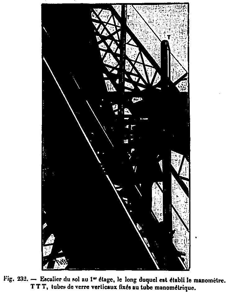
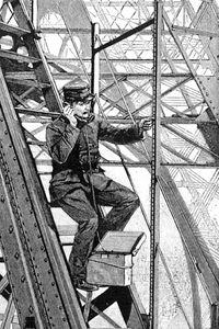
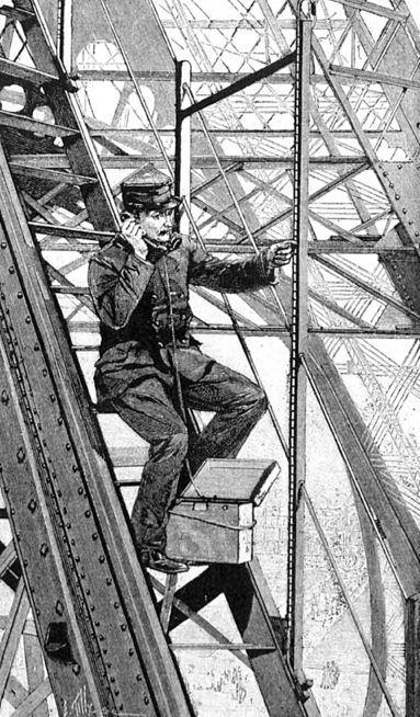
The sloped direction of the tower pillars did not allow the installation of the steel tube in a vertical direction. From the base of the tower to the first platform, that is to say up to a height of about 60 m, this tube is fixed against the inclined plane of one of the rails of the elevator. An iron staircase follows it in all its length.
Between the first and the second platform, that is to say on a height approximately equal to the previous one, the pressure gauge is installed against the spiral staircase. It is divided into several sections, not superimposed on the same vertical, because of the obliquity of the pillar, the manometric tube itself is divided into as many parts and tilts to go from one of these stairs to the other, keeping a slope large enough to ensure the descent of the mercury back. Finally, from the second platform to the summit, the tune is arranged in the same way against the two large vertical spiral staircases.
Easy observation is assured, as we see, from the bottom to the top.
Detail of the device
The opacity of the steel tube opposing the direct reading of the mercury level, arranged at equal distances (about 3m in 3m), on the path of this tube, taps A conical screw which each communicates with a vertical glass tube. This tube is provided with a graduated scale, carefully traced on varnished wood, which experiences only insignificant variations of length by the changes of temperature. When one of these valves is opened, the inside of the steel tube is placed in communication with the glass tube into which the mercury can then penetrate. Figure 330 shows the detail of one of these faucets.
BC is the steel tube, D is the metal nozzle to which the glass tube fits by a rubber, EF is the threaded rod whose conical tip E opens or closes the entrance of the mercury into the glass tube. G leather washers, compressed by tightening the nut H, ensure the tightness of the device. From the base of the Tower to the first platform, as we have said, the direction of the steel tube is tilted. The sketch on the left of figure 231 shows the arrangement of the valves and the glass tubes, against the service staircase, in this part of the apparatus. The sketch to the right of the same figure represents these various organs, from the first floor to the summit. Tubes and taps are protected by a set of wooden chests whose two opposite sides open to allow observations.
To achieve, at a given moment, a determined pressure, simply open the tap of the glass tube which carries the division corresponding to this pressure; the hydraulic pump is made to work, and when the mercury reaches the tap, it rises at the same time into the glass tube and into the steel tube. It is then brought exactly to the desired division, acting very slowly on the hydraulic pump. If, in doing so, the desired level is exceeded, a certain quantity of water is let out by a discharge valve placed in the vicinity of the pump. The escaping liquid thus enters a graduated vertical glass tube where its height indicates the corresponding lowering of the mercury column.

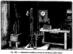
Cette manœuvre, qui se fait dans le laboratoire installé à la base de l'appareil (Voir fig. 233), est rendue très simple au moyen d'un téléphone que l'observateur emporte avec lui, tel qui, à chaque robinet, peut être mis en relation avec le poste inférieur. Dans la figure 231, T représente les pièces de contact destinées à établir la communication téléphonique. (Voir également figure 232 ci-dessous.)
Pressure gauge at high pressures
Pressure gauge at high pressures
Pressure gauge at high pressures
This maneuver, which is done in the laboratory at the base of the apparatus (see Fig. 233), is made very simple by means of a telephone which the observer carries with him, which, at each tap, can be connected with the lower position. In FIG. 231, T represents the contact pieces intended to establish the telephone communication. (See also Figure 232 below.)
Laboratory of the pressure gauge
Laboratory of the pressure gauge

Laboratory of the pressure gauge
If, for any reason, the mercury comes to pass the top of the glass tubes, it pours into another iron return tube, which it sees in XX in the figures attached and which brings it back to the base of the device. The graduated scales that accompany each glass tube, not being always vertically superimposed, we proceeded in the following manner to connect their graduations.
The rating of each point of the Tower is known in a very accurate manner and has provided a number of landmarks. For the connection of two consecutive graduated rulers, two communicating vases filled with water, joined together by a rubber tube, were used to find, for the base of each ladder, the horizontal plane corresponding to the upper level of the ladder. former. The graduation thus made was in agreement with the rating of the various parts of the Tower.
Laboratory
In the West pillar of the Tower, at the base of the pressure gauge, is installed the laboratory (see Fig. 233) which contains the hydraulic impeller pump, the mercury container, the telephone set and other accessories. Among these, we must especially mention a large metal manometer M, related to the compressed liquid. This manometer carries a first graduation in atmospheres; a second graduation corresponds to the order number of the various faucets. We know immediately, in advance, in which glass tube should rise the mercury under a given pressure, which allows to find without hesitation the valve to open to have the exact position of its level.
Corrections
The calculation of the exact value of the pressure, according to the height of the column of mercury raised, requires for each experiment a certain number of corrections which require the knowledge of several elements. The temperature modifies the density of the mercury and varies the height of the tower and consequently of the gauge tube. A simple calculation shows that a temperature difference of 30 ° does not change the height of 1 dm, or 1/3000 of its value. The correction due to the variable density of mercury is more important: it would be about 1/200th for the same difference of 30 °. The measurement of the average temperature necessary for this double correction is obtained by the variation of the electrical resistance which it communicates with the telephone wire which follows the mercurial column all along its course. Recording thermometers placed at each platform give for each experiment a sufficient indication. The other correction elements are the compressibility of mercury, the changes in atmospheric pressure as the column rises.
Conclusions
After the completion of these experiments, Mr. Cailletet handed us the following note summarizing the practical results he obtained:
"The precise indications provided by the pressure gauge established at the Tower have made it possible to graduate the high pressure metal manometers if now employed in various industries. The builders of these machines now have graduated standards directly at the Tower, which allow them to graduate by comparison the manometers coming out of their workshops.
Messrs. Schaeffer and Budenberg supplied us with large metal gauges and pressure measurements up to 400 atmospheres. After several years, these devices have retained their sensitivity and the precision of their indications. It is worth recalling that the metal manometers which were formerly commercially available gave variations in their indications often amounting to 10 or 12%.
The tower manometer was also used to graduate a number of hydrogen gas pressure gauges. These devices, on the sole condition of being always observed at the same temperature, which is obtained by keeping the tube of the apparatus in a body of water at a constant temperature and exactly known, give determinations of a great deal. accuracy. I was able to avoid long-term manipulations of the direct measurement of pressure using the large open-air manometer, and while remaining in the laboratory, measure with the same precision the high pressures under which I operated. In this case, I used two coupled hydrogen manometers, whose simultaneous indications were controlled between them.
It is by this method that, in a work undertaken, with M. Colardeau, on the tension of the steam to its critical point, we have been able to determine with a great precision the corresponding pressures at each of the observed temperatures."
See also: