
The Fives-Lille lifts are two elevators installed in the East and West pillars of the Eiffel Tower in 1900. They replaced the Roux-Combaluzier-Lepape lifts initially installed in these pillars but lacked reliability and speed. The rest of this page is the general and technical description of these two elevators so particular is a description given by Gustave Eiffel himself in his book "The 300m tower".
General provisions
The elevators, the execution of which was entrusted to the Compagnie de Fives-Lille by the Société de la Tour Eiffel, to operate in 1900, are intended for the service of the first and second platforms of the Tower and must ensure traffic of 20,000 people a day both up and down.
These two elevators, installed in the East and West pillars, are independent of each other and their engines are hydraulic presses powered by pumps placed in the engine room of the South Tower pillar. The vehicle planned for these lifts is composed of a chassis carrying two cabins each containing 50 passengers, in addition to the driver's station; this vehicle weighs 9500 kg empty and with 100 passengers 16500 kg. A tangent screw mechanism produces the straightening of the cabins during the course, due to variations of inclination of the track, so as to maintain the horizontal floor.

Fives-Lille
Fives-Lille
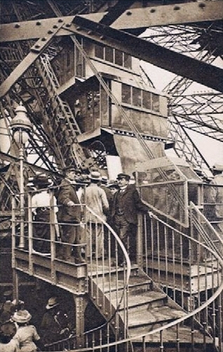
The elevator Fives-Lille in 1899, shortly after the construction of the tower
The track is applied to the trusses that are already part of the frame of the tower; it comprises, in addition to the two rails themselves, two steel beams whose wings are cut in the form of toothed racks with elongate teeth for use at times points of support to the claws of a powerful parachute carried by the vehicle . The undercarriage is suspended by six steel cables divided into two lateral groups of three cables which pass over return pulleys, the main ones, located on the second floor, are 4 m in diameter and have three independent grooves. The cables returned to the foot of the Tower are muffled on pulley systems constituting, with horizontal hydraulic presses, the engine apparatus. The dead strands of the cables are held by a system of hydraulic spreaders ensuring the rigorous distribution of the loads, while leaving each cable the ability to lie down in isolation. The pulleys have three independent grooves for the same purpose.
These high tensile steel wire ropes offer considerable safety; each of them corresponds to 45 tons of rupture, that is to say that only one of the six cables can largely support the vehicle under full load. As the haul pulleys are 3 m in diameter, the winding gives rise, in addition, only to small curvature overvoltages in the elementary wires which have 13 tenths of a millimeter in diameter each. The number of wires is 216 per cable.
The engines are established in the enclave of the foundations of the pillar, at the foot of the path of the elevator, and are further extended inside two covered galleries overflowing under the gardens of the Champ de Mars. They include two horizontal twin hydraulic presses, whose rolled steel plunger plungers are 402 mm in diameter and 16.50 m in travel, acting on the trains of the moving pulleys of the cable haul. To produce the vehicle's climb, these presses are fed by two high-pressure accumulators, containing water at a pressure of about 52 kg per cm2; on the descent, they push the liquid back into a low-pressure accumulator at approximately 18 kg of pressure, thus recovering the energy corresponding to the maneuvering of the dead weight of the vehicle. These accumulators are of considerable size and the most important have been constructed so far. Each one represents an energy accumulation of more than a million kgm.
The distribution units of the power presses are divided into two groups, one for climbing and the other for descent, in order to be completely independent of their functions with the greatest amount of safety. . A steel operating cable established along the rolling path controls these devices by means of servomotors, so that the starting is determined manually by the driver posted on the vehicle. The slowdowns at the stations are automatic.
To comply with the program imposed by the Société de la Tour, the vehicle must make the return trip from the ground to the 2nd floor, twice 130 m in 2 minutes; also counting a minute of stopping at each station for the simultaneous boarding and disembarking of passengers, this is 6 minutes per trip, or 10 trips per hour, corresponding well for each lift to 10,000 people transported per day 10 hours.
The power developed at the vehicle's rise by the high-pressure accumulators, which must charge 4000 liters of water at 52 kg in one minute, is about 500 horses. The descent recovery at the pressure of 18 kg corresponds to about 200 horses.
It follows from it, by difference, a power of 300 horses spent by the vehicle during its actual march; but, as this energy is distributed over a period which represents 6 times the useful time, it is not only that 50 horses which remain to be developed by the pumps of supply in work of hydraulic compression. By increasing this figure of the ordinary coefficients of efficiency of the steam engines which actuate the pumps, we see that the operation of the two elevators will be easily ensured by a motor of only 150 horses.
The parachute of the vehicle is constituted by hydraulic brakes similar to those used in the artillery equipment for the retreat of the cannons on their carriages. For this purpose, four brake pistons paired two by two are arranged in the longitudinal members of the carrier chassis of the cabins; they are integral with articulated claws falling instantly on the rack of the track, in cases of disturbances in the game of the suspension, or in the presence of an exaggerated acceleration of speed on the descent; the vehicle must stop itself and without shock after the 2.50m stroke safety brakes whose delaying action is progressive.
A special device then makes it possible to descend safely, by means of these same brakes then acting as hydraulic cylinders by means of their pistons hooked to the track, following partial races of 2.50 m, up to at the nearest station, without borrowing anything from the cable suspension. Finally, the drive presses and their dispensing devices are provided with safety means such that any irregularity in their operation or in the distribution of loads on the suspension cables immediately determines the automatic and complete shutdown of the entire installation.
The development of this important project, which has not required less than eighteen months of study, is due to the engineers of the Compagnie de Fives-Lille; the execution of the apparatuses, some of which are of colossal dimensions and presented great material difficulties in their realization, is the work of the workshops of this Society; the assembly on site, very dangerous for a large part, was operated by the special staff of the Society of the Tower. These devices are the subject of XXXV to XLV. We will refer to it for the following description of the principal organs.
Main Organs
Cabin
The vehicle (Plate XLIII to XLV) includes a chassis, and two cabins each resting on a movable floor around a horizontal hinge axis. Two connecting rods connect the floors of the cabins forming an articulated parallelogram. A straightening mechanism maintains the horizontal floors during their course on the path of the tower pillar, whose inclination is variable. The straightening movement (XLIII) is obtained by a rod connected to a sector with helical teeth, which is driven by a tangent screw itself receiving the movement of a spur gear meshing with a rack fitted on one side of the path of the road, and reigning throughout the length of the ground at 2nd floor.
The pinion borrows from the rack only insignificant support compared to the significant efforts needed to maintain the cabins in balance on their axes of articulation. The end of the cables, divided into two groups of three, attaches to the side of the chassis. Each cable, after passing through a hawk carried by the spar, ends with a head engaged in a conical part, whose top is turned towards the top of the vehicle. The base of this cone is opposite a metal disc (Fig. 1, XLIV) forming a stop pallet, provided with a rod which is applied on a lever secured to the shaft which controls the release of the safety brakes. There is therefore on each side of the chassis a group of three fasteners applying to a disk. Each fastener is constantly urged towards the bottom of the vehicle by a powerful spring which is supported on the one hand on a base near the top of the cone forming the fastener and on the other hand on a fixed point of the spar. In the event of a cable becoming weaker, the spring would push the clip back, which would cause the stop paddle.
In this last movement, the shaft turns by its lever and triggers the brake system. On the other hand, a centrifugal ball valve with a properly adjusted spring, connected by a gear transmission to one of the load wheels, can also trigger the same brake, if the speed of travel of the vehicle exceeds a certain pace. A hand lever, within the reach of the driver placed on the truck, also provides the means to trigger. this brake in case of imminent danger outside the two causes above.
The safety brake actuated in the preceding conditions has the effect of hooking the vehicle on the teeth of a double steel rack, with long divisions, established along its raceway. This suspension is completely independent of the normal suspension and only immobilizes it after a sufficient course so that the damping of the acquired live power develops only small forces that can not, in any case, damage the parts of the carrier chassis . This hydraulic brake has 4 cylinders applied in pairs under the side beams of the chassis carrying cabins.
The pistons are fitted into the cylinders and are fitted with a pressed leather lining housed in the cylinder head. The pistons are paired in pairs by a common head guided inside the spar. On this head is articulated a kind of robust pallet armed with two mobile horns or claws that can in falling to engage with the teeth of the rack and pinion located on either side of the track of the vehicle. Fasteners attached to the vehicle frame and protruding below the body of the safety racks come to oppose the lifting of the vehicle under the action of pallets.
A strong spring forces the pallets to fall towards the safety toothing by means of levers applied on the claws; but, under the normal conditions of vehicle traffic on its track, a retaining latch keeps them up. If one of the circumstances mentioned above occurs, where the action of the safety brake is necessary, the retaining latch is released from its connections with the suspension cables, either with the centrifugal regulator or with the hand lever: the pallets of the two brake systems fall immediately on the racks, the entire load of the vehicle comes to rely on it by determining the movement of the pistons back in their cylinder.
These, which are filled with glycerin, oppose to the efforts developed the resistance to the flow of this liquid through grooves of decreasing depth practiced in the walls of the cylinders, as in the brakes of the artillery. This results in a uniformly delayed movement of the vehicle, under a constant force supported by the brake devices and the toothing of the racks, and until the final immobilization.
The liquid discharged by the parachute pistons is directed to a small tank placed in the top spacer of the chassis, from where it can be reintegrated back into the cylinders, whose head is in direct communication with this tank. After the operation of the parachute, under the aforementioned conditions, if the engines and the suspension are lacking, the operation is said to rescue the vehicle hooked on the track by the following means: Two steel pipes 25 mm in diameter inside are established at a fixed position along the road, from the ground to the second floor. One of them is in direct communication with the low pressure accumulator, the other communicates with the high pressure accumulators via a differential multiplier device. This device (XLII) can feed the driving, even at the top, with an effective pressure of 75 kg per cm, sufficient to raise the vehicle in full load on its brake pistons acting as jacks. The two so-called rescue lines are equipped with a series of valves spaced 11 m apart, allowing them to be connected with the brakes, using 15 m long flexible steel hoses. A set of needle valves placed on the vehicle at the maneuvering station allows the driver to operate the brakes accordingly for this maneuver, using in addition four hooking claws placed two by two at the lower end of each spar. At the moment when the brake pistons arrive at full speed, and therefore when the vehicle is stopped, the fixed claws of the side members are lowered by hand by a crank in the notches of the side racks, so that it is these new ones. points of support that finally receive the vehicle when it has been lowered a little, to bring the claws fixed to the bottom of the teeth.
Under these conditions, it becomes possible to disengage, by a rearward movement of the vehicle, the first pallets of the toothing of the racks and to raise them, to arm the pistons of the brakes. For this, water is introduced into pressure in the cylinders with the pressure multiplier. Once these pistons are armed again, if we put their pallets into engagement with the racks, we release the claws fixed and the vehicle can then cross on his brakes a distance equal to their race to be received once again on the fixed claws and so on, these successive maneuvers giving the faculty to win the next station, without claiming any help from the ordinary suspension.
The cabins, two in number, which it was important to give the greatest possible lightness, are built with special aluminum profiles, on which is fixed a thin sheet of the same metal. The maneuvering station is placed under the lower cabin, and is attached to the spacer in which are housed the rectifying mechanisms and those triggering the claws of the brake. In this station, there is the steering wheel, used to set the vehicle in motion, either for the ascent or descent, by means of an endless cable moved in one direction or the other by a mechanism of pulleys and racks carried by a front of the post. This mechanism is similar to the one that is installed on the elevators of the Otis system. The endless cable transmits the movement to the distribution members placed in the basement of the stack. This steel cable has a diameter of 12 mm.
Cables
The two groups of 3 suspension cables are each actuated by the engine hydraulic devices placed at the base of the pillar of the Tower, at the foot of the road. The cables pass at the top of the course on two pulleys 4 m in diameter, whose rim is divided into 3 independent gorges.
Other pulleys guide the cables along the path roughly parallel to the tracks. These cables, as we have seen, offer a very high security. They were manufactured by the Ardoisières Company of Angers.
It follows that there is complete safety from the point of view of the suspension of the vehicle. Indeed, the latter in charge exerts maximum traction on the dead end of about 15 tons, 2500 kg for each of the 6 cables on which it is distributed. The section of the cable being 286.6 mm2 the corresponding traction work is 2500 / 286.6 = 8.7 kg. If we add to this fatigue that due to the bending of the cable on pulleys 3 m in diameter and which is: 20 000 x 3000 / 1.3 = 8.66 kg, we arrive at a total of 17.56 kg per square millimeter, which corresponds to about 1/9 of the breaking work we saw being 157 kg.
Driving Presses
Each lift is set in motion by two horizontal hydraulic presses (see XXXV to XXXVII) of 17,542 m of length and 420 mm of internal diameter, resting on raised masonry massifs . The press cylinder is formed of three sections, and it is equipped with a cylinder head in which the arrival of water, and a head bearing a waterproof seal in bronze, with stamped leather. On the cylinder head are arranged a safety valve, in case of rupture of the pipe, and another valve limiting the stroke of the plunger. The head has two locks that also limit the diver's run (see XXXIX).
The assemblies of the cylinder sections serve at the same time, by means of their bronze lining, internal supports for the plunger entirely constructed of rolled steel. The hollow diver is 402 mm in diameter and 18.54 m in total length. It is kept constantly full of water pressure using a small hole in its cylinder head. The head of this piston is connected to a mobile carriage carried by four rollers which roll on a special lane arranged in a masonry underground gallery. After its exit from the cylinder, this piston comes to rest on a series of supports arranged in the gallery, so as to avoid any bending.
The cart (see board XLI) carries four mobile pulleys hauling 3 m of diameter with three independent grooves. Three other identical pulleys, fixed maize, are mounted on the breech of the press. The two groups of 3 cables coming from the vehicle and each corresponding to one of the presses are mittens eight times on these pulleys, so that the necessary stroke for the pistons is equal to 1/8 of that of the vehicle. The latter is 128.61 m, of which 68.41 m from the ground on the first floor and 60.20 m from the first to the second floor. The useful stroke of the plungers is 16,076 m.
The fixed end of the cables is attached, for each group, to a system of three hydraulic tensioners, one for each cable, communicating with each other to ensure the rigorous distribution of the loads while leaving each cable the ease of operation. to lengthen alone. Each tensioner is constituted by a cylindrical body in which is housed a piston provided with a rod. It is on this stem that is attached the end of the dead strand (See board XLI).
Accumulators
The pressurized water that acts on the plunger plunger of the power press comes from two high-pressure accumulators, in which it is discharged by a pump placed in the machine room of the South pillar. The suction of this pump takes place in a low pressure accumulator placed next to the other two. The effective discharge charge of the pump thus corresponds to a water column, measured by the pressure difference between the two kinds of accumulators.
The three accumulators (see board board XXXVIII) are entirely built of cast iron. They have a total common stroke of 5.50 m, a piston diameter of 0.70 m for high pressure and 1.10 m for low pressure. Each accumulator rests on a cast iron base of one piece, 5.50 m in diameter. Cylinders and pistons of high pressure accumulators are in one piece: those of low pressure are in two pieces.
The ballast, whose weight is added to that of the constituent parts of these accumulators, is 166 tons for each of the high-pressure accumulators and 158.6 tons for the low-pressure accumulator. It is contained in a ring-shaped box of 5.50 m diameter resting on a lower cast iron cake suspended by solid bolts to the cap which is attached to the diver's head. This ballast is formed by pigs of cast iron whose intervals are filled with sand.
Each of the accumulators is equipped with a parachute valve, in the event of a pipe break, and in addition with a shut-off valve, used to isolate it from the machine itself (See plate board XXXVIII).
Distribution devices
The two hydraulic drive presses are connected to both high and low pressure accumulator systems, for up or down, by means of pipes connected to start and stop valves which are open or closed at will, while walking the vehicle on the way (See Sm and Pte Board plank board XXXVI, and for board details board XXXIX). These valves, two in number, are each designed to correspond to the passage of the liquid under pressure in one direction, and their opening, which takes place at the time of starting, either to go up or down, is progressive.
On the other hand, the vehicle does not take its full speed apart from the progressive action of these valves that by the intervention of other devices which will be described later: it is the automatic hydraulic regulators, extending until at a speed of 5 m, the slowdown in vehicle speed, from the initial opening of the valve to full operation. Similarly, before stopping at the three stations of the elevator, the regulators in question intervene to slow the speed of the vehicle on a path of 5 m before the total closing of the valve, either on the rise or the descent.
These functions are automatic and therefore of certain regularity. When stopping the vehicle running at full speed, between two consecutive stations, it can be produced by the intervention of its driver: but this mode of stopping does not involve then automatic slowing down, the time to produce it obviously depends on the skill of the driver; this is also without serious difficulty This last faculty can be used more particularly for visiting the roads and the greasing operations of various devices established on the course of the elevator, the walking speed then being as low as one wants, the valves being open only a very small amount.
The water that passed through the start valves and the regulator, before reaching the presses, crosses a so-called press coupler, which aims to equalize the pressures on the section of the engine pistons, in order to make equal the march of the latter and thus ensure an equal distribution of the load on the two groups of the three cables (See M, board XXXVI, and for the details plate board XL).
Stop and start valves
There are two valves of this type, one for the rise of the vehicle thus operating at high pressure and one for the descent, at low pressure. Their entirely identical dispositions are the following ones (See Plate board XXXIX): The shutter itself, circular in shape, rests on a hard bronze seat with a conical bearing; with a very small contact surface and perfectly lapped. This shutter is connected above and below by articulated rods with two balance pistons of the same diameter, which thus make this system independent of the pressures of the liquid, except the friction of the stamped leather linings of the two pistons. This system is placed in a cylindrical sealed body provided with tubings for connection with the general piping, the liquid at the highest pressure being put in relation with the capacity located above the shutter. The flow thus occurs, at the time of opening the valve, in the direction of the top below the shutter.
The underside of the shutter disc is cut into six notches of concave curved shapes (See board XXXIX) which give the maximum section of passage only after a lifting of o mm complete. At the origin of the lifting of the shutter, the liquid can first pass through a true circular crack between the seat and the movable disk, on i or 2 mm in height, then by the six notches, which do not present segmental openings first very weak and enlarging as the valve lifts.
The lifting and closing of this shutter are produced in two opposite directions by a servomotor actuated from the vehicle, as we have seen, using the endless cable. The action of the servo-motor is transmitted to the mechanism located below the body of the valve actuating the lower equilibrium piston to raise it by overcoming the force due to the pressure of the water. For this purpose, a roller (See Fig. 13, board XXXIX), whose axis crosses the extension of the lower piston, rests on a straight cam, a sort of horizontal bar in the form of an inclined plane, which is connected directly to the servomotor by a horizontal axis.
The cam is supported by its lower rectilinear part on a roller carried by a third piston, forming part of a small press housed in the base of the valve. This press is always filled with water pressure, the roller acts as a fixed point, for the cam operating as a corner. When the servomotor pushes the cam, it gradually raises the shutter valve by its inclined plane and opens the valve. The retrograde movement of the cam produces, on the contrary, the closing of the valve. The servomotor spool is actuated by the operating cable using a system of levers and rods. This drawer is not balanced; it always tends to produce the closing of the valve of the step valve.
As a safety device in the case of the softening or breaking of one or more cables, safety valves put the press in the base of the start valve at the outlet; at this moment, this press piston is lowered with the support roller, and the valve goes down on its seat. These safety valves (board XLII) are placed at the head of the cable tensioners and on the coupler.
Any accidental stoppage of the vehicle, cable breakage or abnormal running of the presses, cause their operation and, consequently, the closing of the start valves. In order to order directly from. maneuvering the elevator at low speed, the shut-off and start valves can still be maneuvered from below regardless of the mechanisms described above; it acts for this directly on their shutter to lift it with a nut screwed on the upper part of the main rod, above the upper piston. This maneuver can thus be operated at the foot of the stationary lift and in the absence of any driver placed on the vehicle, which provides the means to operate in the aircraft all desirable checks with complete security; the opening set by hand can be as low and the general running extremely slow.
Automatic speed controllers for drive presses
These devices, two in number, are each appended to one of the stop valves described above, to regulate the flow of the liquid passing either from the high-pressure accumulator to the driving presses, or vice versa. these presses to the accumulator at low pressure, in order to obtain for the pistons connected to the cables of the vehicle a constant speed regardless of the tensile forces that they produce on their hauling (See Rm and W, PI. board XXXVI, and for the details XL board).
All the provisions of these two regulators are identical and the game is based on the following principle: automatically open to the liquid that passes under a pressure drop substantially variable, orifices of adequate section and therefore variable, too, by the antagonism of a spring and a piston actuated by the variable pressure liquid.
The law of variation of the regulating orifices as a function of the pressures of the liquid actuating the driving pistons must be such that the flow rate is strictly constant, the pressures in the reserve accumulators being also constant. In addition, in order to slow down the speed of the vehicle when approaching the stations, when it is switched on or when it arrives, the openings in question are likely to decrease by 4/5 of their normal opening at the corresponding points of the race. engine pistons, by the intervention of a special mechanism acting on these regulators, but without modifying for that the dynamic conditions of the regularization.
1. Cruise control uphill. This device (board XL) consists of a circular shutter in bronze, mobile to the inside of a fixed cylinder in bronze also, against which it is exactly ground. The surfaces of these two cylinders are cut according to circumferentially distributed openings to balance the pressures of the liquid and which can produce, by the superposition of the movable orifices with the fixed orifices, certain regulated combinations. It is by the longitudinal translation of the movable shutter or by its angular rotation that this superposition forms openings of variable sections through which the liquid flows with a rigorously determined flow, and automatically.
For this, the movable cylindrical shutter, fully open at both ends, carries a hub connected by fins to its circumference; a rod fixed to this hub and extended to the upper part of the apparatus forms the adjusting piston called to determine the positions of the movable orifices on the fixed orifices.
This assembly is housed in a cylindrical sealed body provided at its lower part with a tubular in permanent communication with the two drive presses of the elevator via the coupler. The piston, carried externally by the stem of the shutter on its upper face, can receive the action of water under pressure, which is supplied to it by a servomotor which actuates a dispensing spool. This servo-motor puts the upper face of the piston in communication with the pressure or with the evacuation. In the first case, the piston lowers; in the second, it rises, as a result of the pressure acting on the stem of the shutter. In either case, the shutter follows the movement of the piston to which it is attached.
The servo motor operates automatically, by means of a small hydraulic press, or regulating balance, whose diver undergoes all the variations of pressure which take place in the body of the regulator. The regulating scale undergoes the antagonistic action of a stack of Belleville washers. The vertical plunger of the scale and its press body are mounted on the regulator cover. All vertical movement of this plunger is transmitted in the same direction to the antagonist piston of the shutter. The ascent of the latter therefore corresponds to an increase in pressure in the regulator, having produced the lifting of the small plunger and the evacuation of the water located above the counter-piston. The shutter follows all the movements of the small diver. The equilibrium is established when, with the servo motor in its normal position, the regulator water acts on the stem from the bottom up, while the water trapped above the opposing piston opposes any movement.
Around the fixed bronze cylinder concentric with the movable shutter is an annular capacity in aquclle open the orifices which are cut there; it is equipped with a pipe which communicates with the stop and start valve for the climb, itself receiving the liquid supplied by the high pressure accumulator.
It is thus conceivable that, the orifices cut in the movable wall having at different points of their height different sections, their superposition with the fixed orifices can give, as and when the longitudinal displacement of the shutter, sections according to a specific law to achieve a constant flow regardless of the pressure difference under which the flow of liquid occurs at the passage of these openings. When the loading of the vehicle is minimum, and as a result, the pressure difference increases between the accumulator and the driving presses, the plunger goes down, and it is the same with the shutter and its piston, this last then receiving the action of water under pressure. In this case, the orifices decrease in section by the relative displacement of the perforated cylindrical walls; when, on the contrary, the load of the vehicle becomes maximum, the pressure difference decreases, the counter press is put in the evacuation and the shutter is pushed upwards, the section of the orifices increases to maintain the constant flow.
During the normal operation of the elevator, all the holes around the shutter deliver liquid passage simultaneously.
2. Automatic slowdown. At the moment when the slowing down of the vehicle must occur, the shutter undergoes a rotation on itself of an amplitude of 50 °, which blinds nine tenths of the orifices and leaves free passage only on the remaining tenth, without However, modify the height situation and the equilibrium conditions of the moving part of the system. The flow rate of the liquid feeding the presses is thus reduced in about the same proportion and the running speed also becomes about one-tenth of the full flow speed.
This angular rotation of the shutter is determined by means of a large toothed drum whose development is equal to 1 / 25th of the stroke of the vehicle. This drum is provided at its circumference with two corresponding cams, the first at the station of the first and the second at the station of the ground and the second stage. In the rotation of the drum, these cams, which project, come lower the branch of a lever that opens the drawer of a small hydraulic drive. This press, by a combination of connecting rods and lever, turns the moving shutter.
The toothed drum receives the movement of a pinion, which is connected by bevel gears with the lower idler pulley, placed on the large bridge. When the vehicle is on the ground, the cam that corresponds to this station presses on the lever branch of the small power press, and as a result the shutter is turned and most of its orifices is closed. But when the driver maneuver to open the start valve, the water passes through the regulator through the unobstructed ports of the shutter and the engine pistons can start. The toothed drum turns first slowly, and soon the cam of the ground floor escapes the branch of the lever. At this moment, the shutter rotates in the opposite direction and all its orifices become free. As the water has a much larger cross-section, the speed of the engine pistons increases to its normal value. This is the case until, when the vehicle arrives below the first stage, the cam of this station lowers again the branch of the lever, and where the small press closes the shutter again. The complete stop is then obtained by the driver who acts on the stop and start valve, to close it.
3. Regulator for the descent. The provisions of this device are identical to those of the previous one. The main body is also in permanent communication with the driving presses and the outer annular capacitance of the fixed cylinder cut is in relation with the stop and start valve for the descent, which furthermore communicates with the accumulator. low pressure.
The openings of the movable shutter are established in such a way as to decrease in section when the piston rises as a result of the evacuation of the water on its upper face; this occurs for the case of the maximum loading of the vehicle, while the pressure difference between the driving presses and the accumulator increases; on the contrary, the shutter goes down and opens the openings in large, for the minimum of loading of the vehicle. Slowdown around the stations occurs as with the previous device.
Coupler of driving presses
The water that comes out of the cruise control, and that goes to the presses at the time of the climb, or that comes out of the presses to go to the regulator at the time of the descent, goes into the coupler of the driving presses, placed between the two previous devices.
The coupler, which is a common device for ascent and descent, aims to equalize the pressures on the engine pistons. It reduces the arrival of water on the one of the two pistons which would support, at a given moment, a superior effort to the other. This throttling occurs until equal pressure is established on both divers.
The coupler (board XL), fig. 49 to 54) comprises a crew of two horizontal pistons, interconnected by a rigid rod. Each of them slips into a bronze shirt pierced with windows. In normal operation, the two series of windows are placed between the inner faces of the two pistons, where also the pressurized water comes from the regulator.
The piston crew and shirts are contained in a waterproof cast iron body. Each of the two series of windows is located opposite a torus-shaped channel, cast in the body of the coupler. Each torus communicates through a superior line with one of the driving presses. The horizontal pistons are provided with the side of the outer part of an extension passing through a seal, and which receives the action of a counter-spring, housed in a capacity of the cast iron body. This capacity or spring box is connected by a small tube with the anterior face of the pistons of the hydraulic tensioners of the cables. It is filled with water once and for all, as well as the front part of the tensioning cylinders; the initial pressure of the appropriately selected water ensures the tension of the cables. The crew of the two pistons of the coupler is therefore normally in equilibrium.
But if we assume an overvoltage in one of the two groups of cables, the one on the right for example, this overvoltage is transmitted by the tensioners on this side on the outer face of the right piston of the coupler. The crew then moves under this effort, and the piston on the right partially closes the windows corresponding to the right press, creating a pressure drop until the equilibrium is restored on the two divers presses.
In the case of the descent, the water arrives through the torus-shaped ducts, passes into the space between the two pistons and then joins the cruise control for the descent. The coupler is further provided with a safety member. It is a valve that can evacuate at a given moment the safety press, housed in the base of the start valves. The safety valve opens to the evacuation by means of a transmission taken from a rack of the rod which connects the two pistons of the coupler (see details in Fig. 8 to 11, Plate XLII board XLII)). When the crew moves abnormally on one side, the safety valve, by means of the motion transmission, is evacuated for a given movement of the crew, and causes the closing of the start valve.
Complementary components of the distribution
All the organs that we have just examined are interconnected by a pipe, part in cast iron of 200 mm and part in steel of 150 mm. That from the pump to the high pressure accumulators, or from the low pressure accumulator to the pump, is made of steel. On each of these two pipes, there is an isolation valve, which hinders the return of water, either from the high pressure to the pump, or from the pump to the low pressure (see IHP and IBP, board XXXVI), and details XL board), fig. 55 to 58 and 59 to 62).
The pump used is the Worthington system.
The pressurized water that drives all the servo motors of the distribution and safety valves is filtered in a cast iron ladle filled with washed sponges (Fig. 18-20, Pl. board XLII)). The wastewater from these maneuvers is conveyed into a sheet metal discharge tank placed at the base of the pillar (see Fig. 1, board XXXVII).
The three safety valves on the turnbuckles and coupler and the presses on the start valves all communicate with a so-called junction box (see L, board XXXVI), and details board XLII), fig. 12 to 16) which results in the pressurized water that fills these organs. The junction box can be evacuated by hand, by operating the needle p ", which causes, as by a safety valve, the closure of the start valves, so it is a safety organ To complete this description, we will say a word of the pressure multiplier (see V, Pl XXVI, and details Pl XLII, Figs 24 to 54) placed in the elevator room next to the apparatuses. It is intended to supply the water with enough pressure to put it back in a small rescue line placed along the path of the lift, and to act by means of flexible connections in the brake cylinders. This operation may be necessary, in the case where the vehicle is stopped on its way, as a result of the operation of the brakes, and where one wants to make the rescue maneuver, to go up or down at the station closer.
The multiplier consists of a piston with lining, provided with a large rod, and which can move in a cast iron cylinder.
The rod leaves between it and the cylinder an annular space , which is filled, at a given moment, with water at the pressure of the accumulators, and which communicates with the rescue line.
If the same pressure is applied to the same pressure under the piston, that is to say on its solid section, the piston rises, and the water pressure of the annular space is multiplied in the ratio of the inner section of the cylinder to the surface of the annular space. This pressure thus multiplied is sufficient so that the water can, in the worst case, go up to the top of the road, and lift the vehicle load on its brake pistons, acting as jacks. A five-needle dispenser (board XLII)) allows to do all the maneuvers mentioned above.
The installation of the devices is supplemented by a table bearing an indicator of the running of the vehicle, and manometers giving the pressure inside the various hydraulic presses, at stake in the installation.
How the device works
To start the elevator, it is necessary to proceed before filling the low pressure accumulator.
It has been seen that the Worthington pump, which delivers water to the high-pressure accumulators, is designed to operate under a load equal to the pressure difference between the HP accumulators and the LP accumulator. It follows that the latter must be constantly in charge, to allow the running of the pump.
But to do the initial filling, we can not use this pump to supply the high pressure and can not pump into the LP accumulator, because of the isolation valve that prevents the return of water from the pump to these accumulators.
It is necessary to use a small special pump installed near the large, and operating for a delivery pressure of 20 kg per cm3, sufficient to lift the accumulator at low pressure. This pump, by a small pipe of its own, sucks the water into the discharge tank of the elevator, and pushes it back into the high-pressure pipe. The water passes under the HP accumulators, which it can not lift, and arrives in the accumulator BP by a small pipe, which is adapted to the accumulator HP No. 2, and carries the safety filling valve of the latter (see Plate XLII, Fig. 21-25). When the BP accumulator is full, the action of the small pump is stopped and the big one is turned on. As soon as HP batteries are charging, the device is ready for use. The water circuit is shown in detail in the board XXXVI).
We will only say, from the point of view of the operation of the pump, that it operates in an uninterrupted way and allows to maintain in a more or less constant way the HP accumulators at the top of the race, while the BP accumulator is at the bottom of the race. Moreover, safety devices limit the races in each of these directions. For high-pressure accumulators, they cause at the upper limit of their stroke, by means of a discharge safety valve, the evacuation of a certain quantity of water which is sent back into the low-pressure pipe. Likewise, if the LP accumulator is emptying and descending at full speed, the safety filling valve just mentioned opens, and allows the water of the HP No. 2 accumulator to come up. again the BP accumulator. All these functions being automatic, it is no longer necessary to monitor the operation of accumulators of the two pillars.
Efficiency and performance of the device
The vehicle run along the road is, as we have seen, 128.61 m, including 68.41 m from the ground on the 1st floor and 60.20 m from the 1st to the 2nd.
The useful stroke of the power press divers is the eighth of this figure, 16,076 m. The two divers, which are 402 mm in diameter, have a total section of 0.2538 m2. The amount of water spent on a race is therefore 0.2538 x 16.076 = 4.080 m3.
This water, so that the appliances can operate at a temperature below 0 °, is strongly mixed glycerin; the proportion is about 25%. It is always the same water that serves, except losses by leakage of the device; it is supplied in the dumpster at the foot of the elevator. Pressurized water is provided by the HP accumulators, whose capacity must be at least equal to that of both presses.
But the diameter of the pistons of the two accumulators is 700 mm, corresponding to a section of 0.7696 m2. Their stroke is 5.50 m, the amount of water that they can provide together, down to the bottom, is: 0,7696x 5,5 = 4,233 m3.
This quantity of water is sufficient for feeding the presses for a race. In addition, it is necessary that the low pressure accumulator, in which the pump sucks, has itself a capacity equal to the previous one. The diameter of its piston is 1,100 m and its surface of 0,9505 m. The cube corresponding to the 5.50 m race is 5.227 m3. This volume is about 1 m higher than that of HP batteries in order to compensate for all the losses that inevitably occur in the various devices of the distribution. The practical performance of the device is as follows:
Assuming that the water in the presses is at a maximum effective pressure of 50 kg per cma, the engine work expended in a race is: 50 x 2.538 x 16.076 = 200 200 kgm.
This work being provided in one minute, effective time of the course without stop, represents for the presses a power of 200 200 / (60 x 7) = 450 horses. The useful commercial work is reduced to the elevation of 100 passengers to 70 kg, ie 7000 kg of the ground level (+ 35.08) at the 2nd platform (+ 149.25), or on a vertical height of 114.15 m. This work has the value: 7000 x 114.15 = 799.050 kgm and corresponds to a power of 177 horses.
The maximum commercial yield of the elevator at the climb is consequently 700 050/200200 = 0.391. It can therefore vary from 0 to 39%, depending on whether the cabins are empty or full. The walk of the elevator was planned as follows for the Exhibition of 1900.
Under the terms of the contract with Compagnie de Fives-Lille, the total outward and return journey must be made in two minutes of actual time, including a slowdown from the stations as well as before the start. absolute stop on the ground, 1st and 2nd floor, on a course in both directions. The maximum speed of the vehicle on the road should be approximately 2.50 m per second.
The expected durations for the different periods of the course are as follows:
- Climbing the ground on the 1st floor: 30'
- 1st floor stop: 60'
- Climb from 1st floor to 2nd floor: 30'
- Stop at 2nd: 60'
- Descent from 2nd to 1st: 30'
- Stop at 1st: 60'
- Descent from 1st to the ground: 60'
- Stop and change of passengers on the ground: 60'
- Total: 360'
The return trip must be done in 6 minutes. This duration corresponds, at the rate of 100 persons per trip, to a number of 1000 passengers raised per hour.
See also: