
The construction of the pillars form the second major part of the construction of the Eiffel Tower, the first being the foundations. These foundations hide 4 massifs on which are supported the crossbowmen, points of departure of the metallic structure. But this point of contact is quite special, it is described below.
Hydraulic supports and cylinders
We have seen that the supports on which the rafters must rest consisted of a cast iron foot resting on the cut stone and a molded steel counter-shoe penetrating into the shoe and into the inner void of the 'rafter. In the space between the shoe and the counter-shoe, a hydraulic cylinder of 800,000 kg of force could be introduced.
This cylinder is shown in the board VI (Figures 17 to 19). Its cylindrical piston is made of solid cast iron. Its diameter is 0.43 m, its height is 0.34 m. It carries at its lower part a stamped leather maintained by a bolted bronze crown. The body of the cylinder itself is made of wrought iron with a thickness of 95 mm; its outside diameter is 0.62 m and its height is 0.41 m.
The pump that drives the cylinders was carried on a cart to make it transportable; she had a stroke of 6 cm; the diameter of the discharge pipe was 6 mm: it was operated with arms using a large metal lever.
Before leaving the manufacturers' workshops, all the devices had been tested at a pressure of 600 atmospheres, which corresponded to a force of 900 tons on the piston.
The counter hoof of a crossbowman
The counter hoof of a crossbowman
The counter hoof of a crossbowman
This jack was introduced between the two shoes by an opening on one of the walls; the discharge of the water at its lower part made it possible to raise the counter-hoof carrying the crossbowman to a suitable height.
The two cylinders were capable of simultaneously lifting two crossbowmen, even assuming the completed Tower. We have seen, in fact, that the reaction of a crossbowman under the effect of the own weight does not exceed 723 tons. It was therefore possible to produce forces capable of adjusting the relative levels of the feet of the Tower, even after its complete assembly, as one adjusts an ordinary level with the help of screws.
The departure of the batteries of the Eiffel Tower
The departure of the batteries of the Eiffel Tower

The departure of the batteries of the Eiffel Tower, photo taken July 18, 1887.
Photos reproduced with the kind permission of L'Illustration.com.
These supports, most of whose faces were carefully erected, were executed at the Imphy mills. The weights and prices were as follows:
- Cast iron lower shoe: 5 782 Kg to 17.50 = 1 011,85
- Molded steel shoe counter: 2,551 Kg to 46,20 = 1,178.56
- Total: 8,333 Kg to 2,190.41 francs
- How there are 16, the price is 35 046.56 francs
- The 2 cylinders and the pump with its connections and pipes cost: 5 250 francs
The laying of these supports, made with the greatest possible precision, was completed during the course of June, and on the 1st of July we were able to assemble the metal part itself.
Mounting techniques up to the 2nd floor
It was July 1st, 1887, that this assembly began, which was carried out, as and when the deliveries were made by the factory, by the simplest means.
Large, 22 m high sheers were used, which first rested on the ground. This mode of operation, which could be used with some advantage only for limited heights, was all the more applicable in the circumstance that none of the parts to be lifted exceeded the weight of 3,000 kg.
We had set this relatively low weight as a limit that should be exceeded only exceptionally. It was indeed of a nature to give us an economical and rapid assembly; with very heavy parts, it is necessary to use very powerful lifting gear, difficult to install and move; all the installations of the shipyard are affected, they become more important and more expensive. The risk of an accident increases and, if it does, the consequences are much more serious. It is true that the number of rivets to be put on the spot increases because of the decrease in the length of the sections and the greater number of joints; but this disadvantage is very much offset by the ease of maneuvering relatively light parts.
The parts arrived from the factory on trucks that came under the crane placed at the entrance of the yard. From there, they were loaded on wagons which, by four divergent routes, led them to replace each of the batteries. The bigues mounted them in their respective places. The first sections covering the hooves were supported by pieces of wood until the braces joined them and opposed their overthrow. Three successive sections were superimposed, the height of which exceeded the middle of the first panel.
Before moving on to the next sections, all the connecting pieces such as large horizontal beams of the faces, lattices and diagonal pieces were put in place. Then the position of all the parts of this base was checked by rigorous measurements and several times checked. They were made using rules based on the standard meter that was used to trace the pieces in the workshop. When we were assured of the respective positions and levels of all the pieces of this base, we could walk with confidence.
Once the first sections were placed, it was better to use less primitive means, and that was done for the pile 3 by installing, on September 2nd, the first assembly crane that was delivered and will be discussed in detail later.
But as the other cranes were not delivered to us until later, the assembly of the other piles was made in large part with the sheers used for the base, raising them progressively on floors carried by the construction itself.
Model of the thrust pilone
Model of the thrust pilone
Model of the thrust pilone
By one or the other of these means, the successive sections were put in place up to the upper part of the second panel; these sections were connected progressively by the pieces which held them, and one proceeded immediately to their rivur.
But as these sections were inclined about 54 ° along the diagonal plane, it was expected soon a moment when the center of gravity of the amount would fall outside the base formed by the supports and would work the bolts anerage.
The calculation had shown us that we could not exceed the height of 28 m corresponding to the spacer limiting the panel 2; this height was reached on the 10th of October, 1887. The weight of the pieces thus assembled amounted to about 900,000 kg; the number of rivets placed at 98 000. To oppose the overthrow and to continue beyond the assembly to the level of the first platform, it had become necessary to build scaffolding on which the three edges of the uprights closest to the axis of the Tower.
See also: Description of the floors.
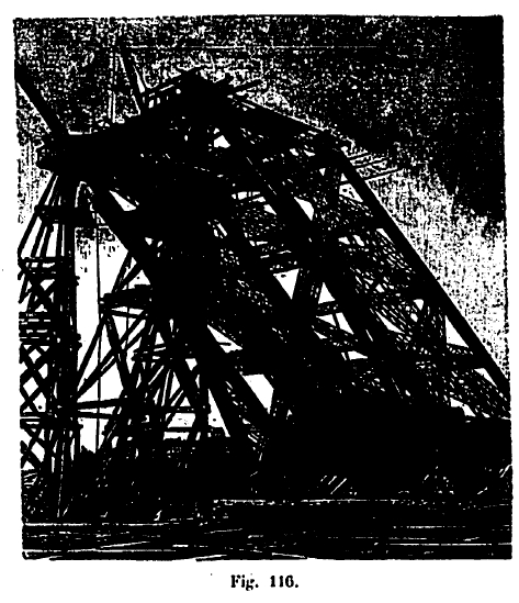
Stopping pylon
These scaffolds were made up of four similar pyramidal towers, so that the reaction due to the inclination, which was to rise for each of the uprights to about 155 tons after the first four panels were erected, was supported by these four pylons, two of which were placed beside the median ridge, and two pylons placed under the two other edges, as shown by the drawing of the model we had drawn up.
These great reactions, in one extreme case, could refer to only two of the pylons, which gave each of them a load of 80 tons. To ensure perfect safety, they were even calculated for a very significantly higher load, about 120 tons.
Their foundation was also to be very firmly established; it required the use of a suitable number of piles beaten to the refusal. This number is 8 per pylon, which gives a pile load of about 15 tons, which is reduced in the maximum case of practice to 10 tons; all the scaffolding of an amount included the use of 32 piles.
These piles, 0.35 m in diameter, had a 6 m long plug for piles 2 and 3 and 9 m for piles 1 and 4. They were beaten by a refusal steam bell 0.10 m for the last ten rounds of a 1000 kg sheep falling by 1.80 m. Some of them for piles 1 and 4, placed above the sewer deflection, have been replaced by pieces of wood descending at the masonry level and established at the bottom of special excavations.
The scaffolding that surmounted them (see board XXV, Fig. 1, 2, 3, 13 and 14) was in the form of a quadrangular pyramid with two vertical faces. Its base was 8,50 m side and its height of 27,40 m. The main pieces were formed by squared beams of 0.27 m on each side; they were braced by 7 rows of 0.25 x 0.12 m and braced on the four sides of the pyramid by 0.22 x 0.22 m wood forming a Saint Andrew cross.
The cube of the piles used for the pylons of the four piles was 85m3. That of each pylon was 23.1m3, ie for one stack 23.12 x 8 = 92.504m3, and for the entire Tower 374 m3 including the floor connecting the pylons.

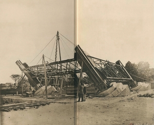
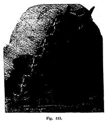
Battery lifting scaffold
Battery lifting scaffold
Battery lifting scaffold
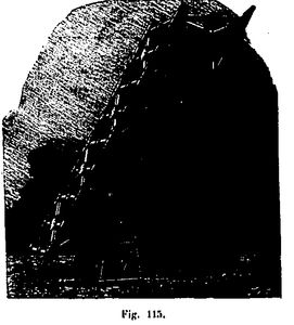
Sandboxes
The iron construction did not rest directly on the heads of the pylons; sandboxes represented in figures 11 and 12 of the board XXV were used as intermediaries.
First, the sections of sturdy provisional iron shoes, shown in plan in figure 5 of plate XXV for the median crossbow, and in figure 9 for the side rafters. The first have a lower horizontal table 14 mm thick, marrying the shape of the rafter and having a length of 1.65 m by 1.03 m. It is held by six strong consoles in plates and angles of 1.33 m in height, riveted on the faces of the crossbowman. The others have a table of 0.877 m by 0.908 m maintained by 3 consoles similar to the first. The consoles are joined together by braces and further connected by temporary angles to the large spacer nearby.
Sandboxes are cylinders made of sheet metal, 0.50 m high and 0.40 m in diameter, which are filled in part with very dry sand and in which a highly fretted oak pad of 0 is introduced. , 50 m high, forming a piston. The cylinder carries at its base a hole that is closed with a wooden plug. If this plug is removed and the sand contained in the cylinder is scratched through the opening, this sand flows, but the flow stops as soon as it is no longer provoked. It follows that you can adjust the descent of the piston with extreme slowness and stop it exactly as you want.
By this means, it was therefore reserved to be able to lower the metal construction carried by the abutment scaffolding, which was to be used later to bring it exactly to its final place. It was also possible to produce bearings using ordinary hydraulic cylinders placed next to the sandboxes and taking their point of support on the top of the pylon. Since, furthermore, the maneuvering of the hydraulic cylinders placed under the supports made it possible to raise or lower the cross-beams of the uprights, it was possible, by the combination of these various modes of action, to have very secure means of adjustment which placed absolutely the hand of the foreman of assembly the movement of these large masses with the aid of three or four men only, without the work being interrupted and without even being noticed.
It was wonderful, says Alfred Picard, to regulate the position of masses so considerable, as a geometer adjusts his spirit level with screws.
1st floor beams assembly
See the board XXV, figure 15 to 18
These beams are 7,834 m high and make an angle of 63,18 ° with the vertical plane; they are located in the planes of the facesexterior and interior of the Tower and consequently 15 m from axis to axis.
Truss spacers, having the same height as the beams, connect them in pairs perpendicularly. All of these beams with their spacers weighed little more than 70 000 kg for one side; but what made their editing difficult wasthe great height to which it was to be made and also the strong inclination of the beams which forced to support them until the momentwhere they had been connected, two by two, by their spacers. Finally, for reasons of economy, the scaffolding on which they were mountedhad not been established over the entire length of the beams, which forced to begin the assembly of the beams by the central partand to make them walk progressively by the two ends while going up cantilever their extreme parts until their meetingwith the main pillars.
To this end, four similar scaffolds had been constructed, one in each face of the Tower. They were 41 m high and consisted of nine 25x25 uprights, spaced 7.50 m in one direction and 7.75 m in the other. Because of the small loads the scaffolding had to bear, it had not been thought advisable to bury these posts on piles that had been beaten in the ground, as had been done for the stop scaffolds; they were simply leaning on soles resting on the ground. They were braced in all directions by crosses of St. Andrew formed by woods of 0.22 x0.11 m and connected horizontally by seven courses of months of 0.25 m x 0.12 m. Struts arranged at their upper part allowed to give the mounting platform 28.50 m long and 22.40 m wide. Finally another series of struts rising a little lower than those who supported the mounting platform supported a hanger, which was later used to set up the central part of the decorative arches. Each scaffolding consisted of 215 m3 of wood, giving a total cube of 885 m2 for all four, including 185 m3 of decking and 25 m2 of rigging.
The actual mounting of the horizontal beams did not offer anything special; it was carried out by means of goats established on the platform. When it was finished, we proceeded to connect these beams with the amounts.
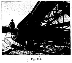
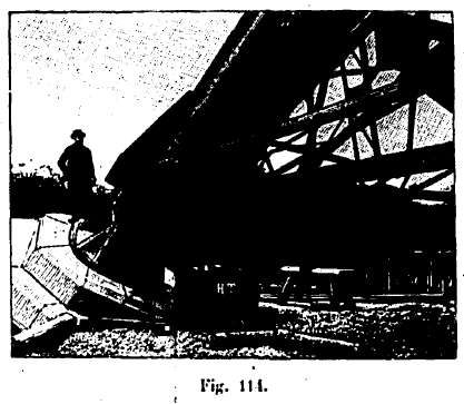
This was the particularly difficult moment of the operation. The four uprights overhanging the abutment scaffolds of an overhang of about 26 m seemed, with their great inclination, to be about to overturn. At that time they were 58 m long and weighed nearly 400,000 kg. It was these great prisms of enormous weight, whose dimensions were close to those of the towers of Notre-Dame, that it was a question of maneuvering in such a way as to bring them in contact with the horizontal beams with which they had to go. junction, and it was necessary to be able to operate these movements with a precision such that the holes rivets pierced in advance in the gussets of junction beams and amounts are absolutely opposite each other. It is by means of the sandboxes carried by the stop scaffolding and by means of the hydraulic presses, which we have described previously, that this maneuver was carried out. Acting sometimes on a crossbowman, sometimes on another, either to lower it or to raise it, it was possible to obtain the desired contact.
The layout of the four uprights was so exact, their execution so perfect, that it was possible to assemble them with the belt girders without the need for a chisel to retouch the parts in contact, nor a reamer to increase the diameter of the holes that were to receive the joining rivets (Fig. 119).
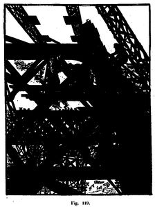
Diagram of elevation of the crane
Diagram of elevation of the crane

Diagram of the crane used in the construction of the Eiffel Tower
It was the most delicate operation of the Tower's assembly and, as soon as it was successful, the final success was assured. The uprights were joined by the first girders-belts formed like a solid table, largely seated and whose sight alone was enough to avoid any fear of overthrow. There was no longer any fear of a general accident, and the partial accidents that might still have occurred would not have been likely to compromise the completion of the construction.
Once the junctions of the uprights and the first horizontal beams were made, the installation of the numerous beams forming the floors of the first floor was done without any difficulty. Men worked on timber platforms, as conveniently installed as in a workshop. We arrived at the level of the first floor, 57.63 m above the ground of the Champ-de-Mars.
See also: