
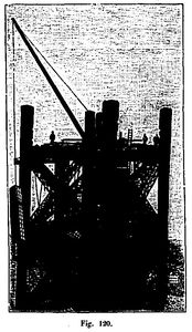
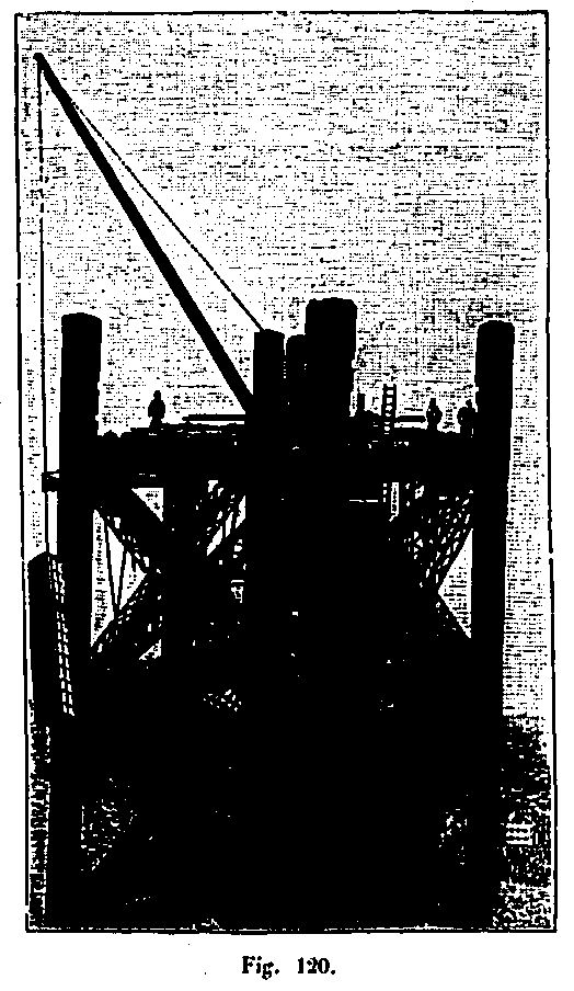
Assembly from 1st to 2nd floor
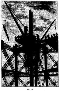
The assembly of the part of the uprights between the first and the second floor (see Fig. 120) continued as for the lower part, by means of the cranes that one hitched progressively on the paths of the elevators. Only, as the inclination of the uprights varied from one panel to another, it was necessary to bring the pivots of the cranes into the vertical, each time that one had risen to the height of a panel. This operation was also done with the greatest ease, by maneuvering the screw fixed to the base of the pivot, as we have explained previously in the description of the mounting cranes.
Assembly of the first floor
Assembly of the first floor
Detail of the assembly of the first floor
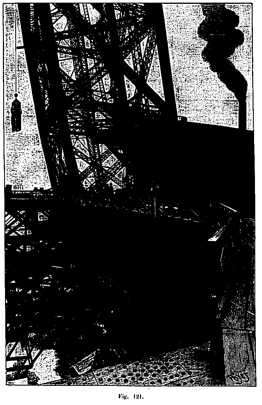
As one rose, the time required for lifting the pieces increased; in addition, the hoisting chain becoming much longer, added a significant weight to the parts that the cranes lifted. To overcome these two disadvantages: too slow the rise and increase loads to hoist, it establishes a steam elevator at the first floor.
This lift (see Fig. 121) was located on the inside edge of the first floor floor facing the Military School. From that moment, all the materials were brought by a track below this elevator, instead of being distributed between the four uprights as before. Attached to the chain of the freight elevator, they were quickly raised to the level of the first floor; arrived there, they were placed on wagons which, following a circular path carried by the floor of the first floor, were going to lead them to the right of the amount for which they were intended, from where they were taken again by the crane of assembly, which put them in place (Figures 1 and 2, board XXIV).
By doing this, we reached the second floor, that is 115.21 m above the ground.
See also: Description of the floors.
Assembly from 2nd to 3rd floor
We have seen, in the general description of the Tower, that from the second floor, the building system changes completely. The four separate uprights disappear, their outer faces merge two by two in one, so that, up to the third floor, the upper part of the Tower forms a large empty cage in the form of a truncated pyramid. Elevator runways no longer exist because the system used for the upper part has suspended cabins and no longer wheeled cabs. It can be seen from this that the method used for the assembly had to be radically modified from the second floor.
Construction of the 2nd floor
Construction of the 2nd floor

Construction of the 2nd floor, may 15th, 1888
It was no longer possible to keep the four cranes. The horizontal section of the Tower was narrowing more and more, and two cranes became sufficient to serve all points of the construction. It was a matter of building a vertical path for them, instead of the lifts on which they had climbed up to that point.
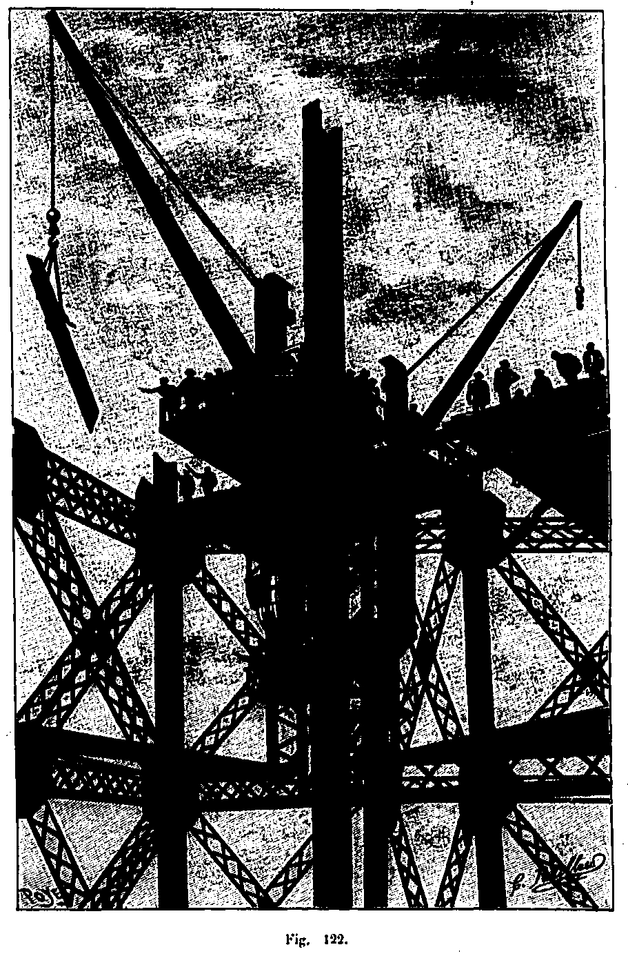
In the axis of the Tower reigns, from the second to the third floor, a vertical pillar that serves as the main guide to the elevator cabins. It is formed by a box beam whose trellis cores are 0.80 m high and the soles are 0.60 m wide. The width of the soles was not so great that they could be used directly as support surface for the crane frames, which had been constructed to slide on the beams of the lower elevators separated by 3.80 m; but, by applying to these soles frames whose vertical borders presented precisely this spacing of 3.80m, it was possible to create a suitable path for hauling the two cranes which were to complete the assembly (see Fig. 122 below and the board XXIV, Fig. 5 to 13).
Elevators of the Eiffel tower
Elevators of the Eiffel tower
Elevators of the Eiffel tower
These frames or frames (Figure 8 to 12) were arranged on each side of the central guide pillar elevators. They consisted of the two curbs on which were bolted the frame of the cranes and a third median beam which attached to the sole of the guide pillar. These three beams were interconnected by horizontal braces and a cross angle. The height of the frames was 3m. Three overlapping frames formed a vertical path of 9m in height, according to which crane maneuvers could be done in exactly the same way, and with the same safety as on the beams of the lower lifts.
The frames on either side of the guide pillar were joined laterally by an angle grid to form a rectangular cage, in the middle of which the central pillar was trapped. At the same time, the two cranes were hoisted up, which balanced out empty, and tended to bend the pillar only when one of them was in charge. The bending of the pillar was fought first by the large spacers that connect it, in each plane of bracing, at the corners of the Tower, and then by additional and temporary braces which, staggered by an end on the part central of the large spacer, were attached by the other end to the crossbowmen of the Tower.
When the cranes had gone through a set of 9m frames, it was used to get a second game in the same way. height after the first. Cranes were raised on these new frames; the old ones were becoming available, waiting for them to be dismantled, still by means of cranes, to be reassembled above.
The lifting of the cranes, including moving a complete set of frames 9 m in height, required only thirty hours, three days of ten hours with ten men, time certainly very short if one considers that it was a question of moving, on successive occasions, a group of machines whose total weight reached 45 000 kg. Cranes once installed could, without changing altitude, mount an entire panel.
Cranes of the Eiffel Tower
Cranes of the Eiffel Tower
Cranes of the Eiffel Tower
Just as a steam hoister had been installed on the first floor, so had successively installed one on the second floor and a third on the intermediate floor 197m high. It is at the level of this floor that the cabins of the higher lifts meet and the transshipment of the passengers.
Proceeding as we have just said, we arrived at the third floor platform at the end of February 1889, and a month later the assembly was completely finished.
See also: Description of the floors.
Various editing details
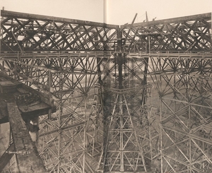
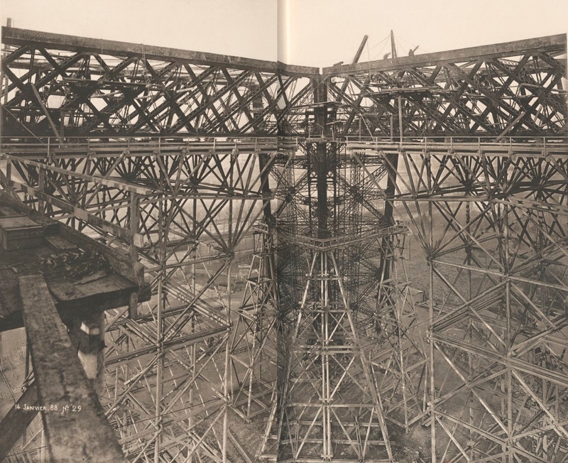
One of the most active periods was the simultaneous assembly of the uprights and beams of the first platform. In addition to the cranes on the uprights, there were two goats installed by scaffolding, so that the irons could be mounted at heights of 45 to 56 m by twelve devices at a time. In spite of the bad season, during each of the months of January, February and March, 650 tons of iron were able to rise. Because of the great difficulties of the work, this tonnage is considerable.
As the joists were laid in the first platform, the masons built the hollow brick slab, Perrière system; An absolutely closed platform was thus built on which a new supply site supplied by the first stage steam elevator was installed. it included two Bernier winches powered by a 12 horsepower locomobile.
Due to its weight (6,000 Kg), the first lattice spacer that connects the pillars to the bottom of the panel 10, was assembled on the floor of the first floor and set up with two cranes moored at each end.
The beams on the second floor were cantilevered by the cranes. The differences which existed in the spacing of the pillars with respect to the calculated dimensions were absolutely insignificant, and the assembly was done by ordinary means, jacks and pins. A leveling done on the top of the sections having made it possible to recognize that the horizontality was perfect, it was possible definitively to settle the wedges placed between the support with the base and the counter-hoof and to make sure, by means of manometers placed on the pump, that the load on each rafter was substantially the same. There was no longer any problem in removing the sandboxes and abandoning the building itself.
The demolition of the scaffolding was done without any difficulty, taking on the pillars of the Tower the support of the return pulleys of the cables used for the descent of the woods.
The part of the arches placed between the big scaffoldings and the pylons, was mounted in cantilever. For the intermediate parts, the assembly was done during the assembly of the beams of the second floor, on the scaffolding itself, which had been arranged for this purpose.
The assembly of the panel 13 and a portion of the panel 14 was made with the arrangement of the cranes used on the lower panels, by hoisting them to the top of the beams of the lifts that exceeded the level of the platform.
In the meantime, with the goats, the new route was laid on the central post; when it was in place, the two cranes which were to climb to the top were installed with the help of the cranes of piles 2 and 4, which stopped at this height.
As it had been done on the first floor, the second, and as soon as it was possible, the Perrière slab was established; A new platform was thus built which received a second steam lift for the supply of the irons. This second lift was almost similar to the first, except that the pieces, on their arrival, raised a hatch which was closed at once the room passed, and on which came to be placed the carriages intended to receive the load.
A circular lane used to drive the parts to the most suitable points to be taken over by the cranes.
The assembly of the section C of the panels 13, 14 and 15, was done using the goats: one should have, indeed, give the cranes a flight too considerable to reach these points.
Construction of the 1st floor
Construction of the 1st floor
Construction of the 1st floor, january 14th, 1888
At an elevation of 80 m above the second floor, that is to say at the intermediate platform, a complete wooden floor is established, constituting a new supply platform, which is equipped with a third steam lift similar to the first two, except that it had only one winch.
In order to supply the machines for these hoists and to always have water on the scaffolding in the event of fire, a tank was installed on the second floor, powered by a Thirion pump. A second pump pumped the water to another tank at the intermediate platform.
Above the third floor, the cranes could no longer orient, one of them was demolished and, with that which remained, we put up the irons of the upper part, which were put in place using goats. Finally, for the dome of the lighthouse, we installed a bigueton with a hoist.
The goat that was installed was used to dismantle the crane and assemble all the materials for this platform.
See also: