
For the assembly of the parts from the base for the pile 3 and from the second panel for the others, we used special cranes, which require that we stop there rather long, because they were used until the completion of the works and they rendered us the greatest services. They were studied with great care and carried out with rare success by Mr. Guyenet, engineer-builder, according to the program that we had traced to him.
We have seen that inside each upright and above the crossbow closest to the center of the tower are the elevator paths. They are two large beams inclined in the same direction as the crossbow, having a height of 1.30 m, and are like the gigantic rails of the track followed by the elevator cabins.
It was the same path that was to be used as it was put in place to serve as a crane way.
Since the latter had to be able to bring to their final position all the parts making up the upright, and in particular the beams of the elevators, she herself was going up the road in which she had to be hoisted.
Each pillar had to be equipped with a similar crane, with a force of 3,000 kg and a range of 5.5 m to 12 m, to easily serve all points of the installation plane included between the four crossbowmen in an amount.
As a result of these conditions, these cranes had to be rotating and with variable range: they had, moreover, because of changes in the inclination of the road to be covered, to be provided with a mechanism making it possible to easily restore the verticality of their pivot, and finally carry the machine used to hoist them on the beams of the lifts.
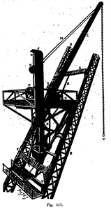
Diagram of the crane
Diagram of the crane

Diagram of the crane
The principle of the crane, as realized by M. Guyenet (see Fig. 117, above), consists in arranging on the elevator tracks an iron frame, C, which can either slide on these roads, either bolted to it, and to which is suspended by a hinge at its upper part, an iron hood, D, having the shape of overturned pyramid trunk affected by the ordinary hood intended to carry the burdens; in this hood is installed the crane. At 2.50 m higher, measured according to the inclination, is an iron crossbar, G, which can also either slide on the path or bolt there. The crossbar and the frame are connected by a strong screw, H. By unbolting the frame and turning the screw, we can bring it into contact with the cross, it is bolted in this position; we can then, after unbolting the crossbar, turn the screw in the opposite direction and, this time taking its support on the frame, bring it to 2.50 m higher. The entire device will have risen by 2.50 m.
In order to operate safely and to ensure that the chassis carrying the crane is not simply suspended from a moving screw, a crossbar V similar to the one at the top, 0.50 m high, was placed at the bottom. , carrying cylinders with short stroke, following the chassis in its rise and ready to receive it in case of rupture of the screw.
By operating alternately in one direction or the other the large screw and simultaneously the small screws, for which the maneuvering of the cross is more frequent, we arrive, by a series of progressive paths, to mount the set of the device at all heights.
The simple exposition of this principle will facilitate the understanding of the following description, of this apparatus represented in cavalier perspective in the figure above and in all the details in the board XXIV, fig. 1, 2, 3, 4 and 13.
We borrow it, as well as some other details that follow, to a communication made in 1890 to the National Industry Incentive Company, by Mr. E. Nouguier, our engineer, whom we had charged with the direction of assembly work.
The device includes:
- A mobile chassis, CC, which is bolted to the elevator beams when the crane is working and can slide on these same beams, when it becomes necessary to raise the level of the crane.
- A set of metal parts forming a kind of hood, D, carrying, at its upper part, the platform U of the crane and, at its lower part, the crane of the crane pivot. This hood is suspended from the chassis CC by two joints located in the plane of the platform and is connected to the bottom rail of the chassis by a screw. It is easily understood from the inspection of the figure that a man placed on the special floor F can, by maneuvering this screw, vary the position of the hood and, consequently, bring the pivot of the crane into the vertical , regardless of the slope of the elevator lane.
- The crane itself. This consists of: a pivot, JJ, which rests, at its base, on the crapaudine carried by the hood and which is held in its middle by a rolling circle placed in the thickness of the floor of the platform; shape: of an arrow L carrying the hoist winch S, arrow which is connected to the pivot J, at its lower end, by a hinge, and at its upper end, by two tie rods, M, assembled on a wheelset, N, which can move along the pivot. This axle carries a nut actuated by a screw, O. A flywheel, P, on the axis of which is a pinion meshing with a conical gear fixed to the screw, makes it possible, by raising or lowering the axle N, to increase or decrease the flight of the crane. By acting on the same wheel P, it is also possible to communicate a rotational movement to the crane. For this purpose, it starts by disengaging the lifting mechanism and then a second pinion mounted on the axis of the steering wheel engages with a conical wheel fixed on a vertical shaft, whose lower end carries a pinion controlling a circular rack making part of the rolling circle. A ratchet and a pawl prevent the crane from turning when given the proper orientation.
The movement of the crane on the elevators path takes place by means of the large towing screw H and the two safety cylinders.
H-bolt passes through a nut connected by two tie rods to the upper crossmember of chassis C; it carries at its head a cross or mobile bed base, G, which can slide on the elevator beams B, or bolt on them. A ratchet, equipped with a lever that is maneuvered from the platform U of the crane, serves to actuate this screw.
The safety cylinders V act below the mobile frame, along the axis of the elevator beams; they are screw jacks connected by a spacer X and which carry at their head a foot abutment which is applied against the lower crossmember of the mobile chassis CC. The spacer and the stops can take turns, either slide on the elevator beams, or be fixed on them with bolts.
When one wanted to raise the crane, one began by orienting it so that its flight came to be placed in the axis of the way of the elevators while remaining turned towards the interior of the Tower. It then acted on the big screw H so as to bring the crosshead G at full stroke to 2.50 m higher than in its previous position. It was bolted to the elevator beams BB and the mobile chassis CC was then unbolted, which was then suspended on the screw H and supported at its base by the safety cylinders V. The towing screw was again maneuvered. H, and the CC chassis mounted sliding on the BB beams removing with him the crane and its hood. Men installed on the floor Z followed with the safety cylinders the upward movement always keeping the head of these cylinders in contact with the base of the frame, so that the latter, in case of rupture of the screw H, would not could not fall, held that it was by the two cylinders V.
The race of these was only 0.50 m, which required a number of times to complete the entire movement of the crane. When these cylinders had reached the bottom of the race, their stops were bolted to the BB beams, their X spacers were unbolted, which during the hoisting had remained fixed on these same BB beams. While maneuvering the cylinders, in the opposite direction, they made raise the spacer of all the height of their race. It was reboutonnaient on the BB beams, unbolted the stops and began a new step forward, by pressing again and simultaneously the big screw H and the two safety cylinders V.
The lifting operation of the crane lasted about 18 hours and employed 10 men, in addition to the team leader.
The assembly of all the constituent parts of the amounts of the Tower was made with the cranes of which we have just given the description. The crossbowmen were commenced, and after them the lattice bars and the struts which, by uniting the portions of the pillars already assembled, obliged them to come and occupy their exact position. Behind the teams of fitters came the teams of riveters, who replaced the provisional bolts, with which the first had made the junctions of the parts, by hot rivets assuring the true and final connection of the parts between them (Fig. 118).

Diagram of the mounting crane
Diagram of the mounting crane
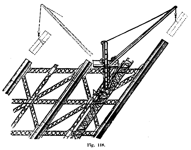
Diagram of the mounting crane
Below each crane, at the level of the horizontal braces, was established a nearly general floor overflowing cantilevered all around the upright. In addition, to make the joints and assemblies rivill, small flying scaffolds were always placed at a short distance from the general floor.
Moving these floors and scaffolding was done using cranes.
The assembly of the stair followed as much as possible that of the amounts, so that men, to go to their post of work, used these stairs over almost the entire height of the route and had to use the ladders only towards the end of their ascent.
While, by the means we have just indicated, the four lower panels of the uprights were mounted, the first horizontal beams were made to connect them 47.90 m above the ground.
More about crane maneuvers
The weight of each empty crane reached 15,000 kg; also the connection of the frame to the elevator beams required not less than 170 bolts of 20 mm steel.
The nominal load of 3,000 Kg was often exceeded, and actually reached 4,000 Kg. In fact, the sections of the panel 5, which weighed 3,200 Kg, were suspended by a 22mm calibrated link chain. length of 70 m, as its weight per running meter was 11 kg, its total weight was about 800 kg with the counterweight, so the winch that was adapted was a Bernier winch (calibrated chain meshing with a walnut) of 4,000 Kg of force, but care was taken to reduce the fatigue of the crane as it mounted this charge, to orient the flight towards the axis of the Tower and to raise the arrow as much as possible.
The hoisting took place when the panel was erected, the average height was 11 m, and when the elevator beams were put in place and riveted. First of all, the safety cylinders were brought into contact, and then, by directing the crane toward the axis of the tower and raising the fly as far as it could go, the beam was raised, which was attached to the beams by 32 bolts of steel. 20 mm. The chassis was unbolted, and the hoisting was carried out by means of six men acting on a lever of 1.25 m, engaged in the pawl of the lifting screw. Each lever stroke lifted the crane by 12 mm. Every 0.50 m, the safety stops being exhausted, we placed 20 bolts and 10 pins in the frame and resumed the rigging. The lift on the height of a panel lasted about eighteen hours with ten men and a team leader.
In the upper part, the crane path was formed by a double row of six rectangular, interchangeable 3.96 m long chassis, attached to the central post by 384 steel 20 mm bolts; the length of this path was 23.77 m. This great length of track was motivated by the need to distribute the weight of all this equipment of chassis and cranes over a sufficient length.
As a precaution, during the hoisting of the cranes, 4 rope hoists with 3 strands of 8000 Kg each were installed. These hoists were controlled by drum winches fixed on the horizontal bracing of the mounted panel. While helping to hoist, these hoists were especially prepared to oppose overturning and, in the unlikely event of simultaneous breakage of the screw and the safety lock, they could have supported the load of the crane.
As the sections of the central post were laid, the lower frame was removed and replaced at the top of the post, and the hoist was hoisted as on the elevator beams. . To withstand the twisting moment given by the movement of the pawls during hoisting, the frames were connected by rigid bars to the brace gussets of the cross sections of the intermediate rafters.
This maneuver, which was relatively delicate, has always operated normally and never gave rise to any accident. The fall of the cranes during one of these hîssages, would have had consequences so disastrous, either for the personnel, or for the work itself, that it would have destroyed in part, that one had accumulated for the avoid all possible material precautions; the operation, entrusted to the safest and most experienced men, was done with the constant presence of the site manager.
The duration of a ten-meter lifting operation with ten men and a team leader was about thirty hours, three days, one for the chassis change and two for the lifting. of the crane.
See also: