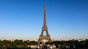

Calcul des forces de la tour Eiffel
When one wants to calculate the sections and the shape that a metallic tower like the Eiffel Tower must take, it is necessary above all to take into account two types of forces to which it must resist, apart from the effects of the temperature: the forces due to the loads vertical and those due to the wind. The latter are largely the most important: in the upper parts of the Tower the working coefficient due to the wind is almost triple that due to the loads. In the lower parts, it still remains equal to about half of it. To be clear, the effort due to the loads corresponds to the weight of the tower on itself, it does not have to collapse. The effort due to the wind is aptly named, it is the lateral stress that it undergoes due to the wind.
These two types of load are described and calculated in the following texts, but first of all it is necessary to determine how is the structure of the Eiffel Tower, to understand the calculations. So there are three parts on this page: The composition of the tower, whose text is below, then the effect of the load and finally the effect of the wind, whose calculations are so complex that they are accompanied many explanatory diagrams as well as tables giving the results of the calculations.
But first of all, you have to start by explaining the general shape of a metal tower if you want to understand how the Eiffel Tower is made.
General shapes of a metal tower with or without apron to support
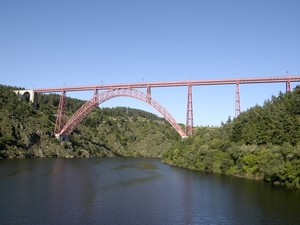
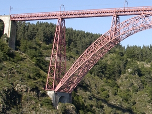
The viaduct of Garabit
The viaduct of Garabit

The viaduct of Garabit, by Gustave Eiffel
The first thing is to know that before embarking on drawing plans for the tower, Gustave Eiffel had already made many metal constructions, especially for viaducts for railways. He used for that cast iron piles in the form of rectangular columns, regularly joined by iron spacers. The general shape is a stack of quadrangular boxes open on the inside of the stack, and into which are inserted long square section bracing bars capable of working both on the compression and extension under the efforts of the wind. This type of construction had become usual, Eiffel thus achieving the bridge of the Douro in Porto (whose central arch has a metal arch of 160 meters opening and 42m 50 of arrow), and the viaduct of Garabit (in the Cantal ) which crosses the Truyère at a height of 122 meters. This viaduct is designed in the same way as the Douro, with a length of 564 meters and a parabolic central arch of 165 meters opening and 57 meters of arrow. The viaduct of Garabit is the archetype of the Eiffel viaduct model, it has piles in boxes of 61 meters, only for the metal part. Such a height can be achieved thanks to their rigidity, and in addition, their maintenance is very easy.
But if you want to tackle even greater heights and exceed 100 meters for example, it becomes necessary to change the construction mode. In fact, if the feet of the pile reach a width of 25 to 30 meters necessary for these heights, the bracing diagonals which bring them together take such a length that, even established in the shape of a box, they become inefficient and heavy, we must therefore remove them and give the pile a shape such that all the sharp forces come to concentrate in its edges. It must therefore be reduced to four large amounts clear of any bracing mesh, and simply joined by a few horizontal belts widely spaced.
If the pile supports a metal deck and we take into account the effect of the wind on the deck (always more important than the effect of the wind on the pile itself) it will suffice, to be able to remove the bracing bars vertical faces, to pass the two axes of the rafters by a single point placed on the top of this pile. In this case the horizontal force of the wind may be directly decomposed along the axes of these crossbowmen, and that they will not be subjected to any shearing force.
If, on the contrary, it is a very large pile, such as the Eiffel Tower, there is no longer at the top the horizontal reaction of the wind on the deck, but simply the action of the wind on the pile. -even. In order to remove the lattice bars, it is necessary to give the uprights a curvature such that the tangents to these uprights, carried out at points situated at the same height, always meet at the point of passage of the resultant of the actions which the wind exerts. on the part of the pile that is above the points considered.
Finally, if we want to take into account both the action of the wind on the upper deck and the one experienced by the pile itself, the outer curve of the pile is less inflected and is close to the straight line.
Stack of the viaduct of Garabit, by Gustave Eiffel
Stack of the viaduct of Garabit, by Gustave Eiffel

Stack of the viaduct of Garabit, by Gustave Eiffel
If you do not understand, it does not matter, look at the image of the pile of the viaduct Garabit above, it represents one of the piles of the viaduct with its box shape. Otherwise, you have come to the conclusion that non-braced and curved-edge pile constructions are the solutions for building metal towers of any height, such as the Eiffel Tower. So we have the general principle of construction. We can go to plan.
Composition of elements of the tower
First of all, we must begin by understanding how the tower was made, from a general point of view. It is only a succession of 29 panels (sort of horizontal slices). For the calculation, we take into account the notion of sections, which is explained below. Help yourself explanatory boards, they are there to enlighten the subject.
Division into panels and sections
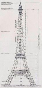
Elevation
Elevation
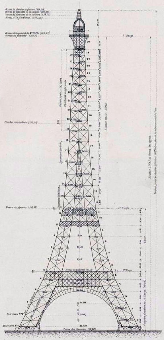
Elevation of the Eiffel tower, panel by panel
As for the method of calculation, it differs according to whether we consider the upper part of the Tower, in which all the rafters are joined together by a lattice (see the description for more detail), or the lower part formed by four piles isolated, each of which consists of four crossbowmen joined by lattices. The first part extends from the campanile to the level of the second platform; the second goes from this level to that of the supports.
The metal frame is divided into panels formed by the indeformable trapeziums determined by the horizontal struts, the portions of inclined rafters and the lattice bars forming diagonals. These signs are numbered from 1 to 29, starting from the bottom (see board XXXI).
For the calculations of the efforts in the crossbowmen and to avoid any confusion, the sections were numbered differently, by designating them by Roman numerals and going from top to bottom. Section I is the one at the bottom of the panel 28, section II at the bottom of the panel 27, etc. Section XVII is located at the bottom of the panel 11 at the second platform and separates the upper part of the tower from the lower part. The last section is No. XXVIII and is located at the bottom of the last panel, at the level of the spacer that brings the supports.
Crossbow and truss sections
These sections are drawn and calculated in board XXXI, which dispenses with giving a detailed description.
Crossbowmen, upper part
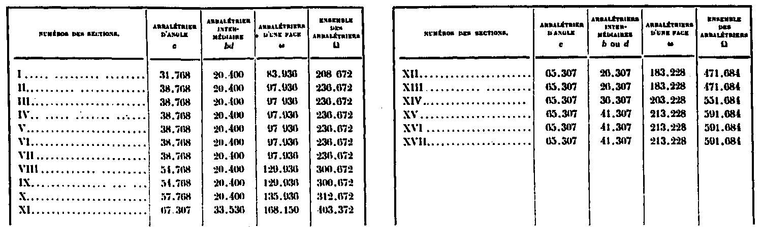
The diagrams Figures 1 and 2 indicate the arrangement of the rafters, which include, at the second platform, four rafters c angle, and two intermediate rafters b and d on each side. From Section XI, the intermediate rafters meet in one comic strip.
We will designate by ω the surface of all the rafters of a face and by Ω the surface of all the rafters of the four faces.
Table of cross sectional areas of the rafters at the top, in square millimeters
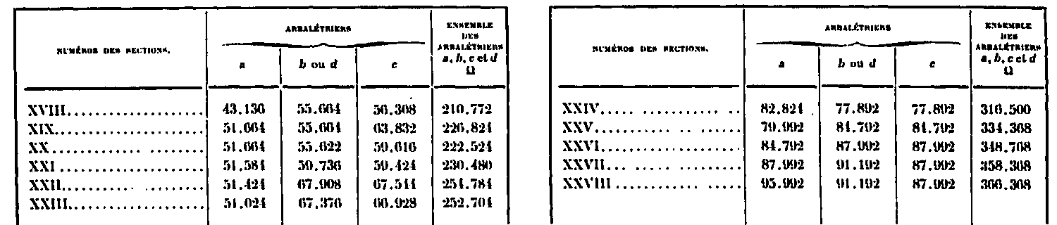
Crossbowmen, lower part
The four studs that make up the frame of the Tower below the second platform are similar. They are each composed of 4 crossbowmen of angle a, b, c, d, whose composition is given in the board XXXI. In the following table we summarize the surfaces of the sections of each rafter and their total section area Ω.
Table of cross sectional areas of the rafters at the bottom, in square millimeters
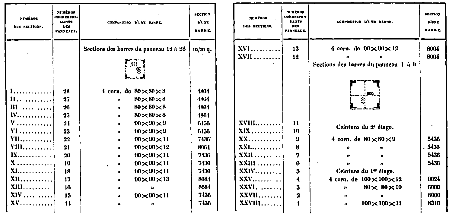
lattice
The lattice bars are all box-shaped and consist of 4 corner angles joined by a small lattice. We give below the dimensions of these angles, as well as the surface of the sections of the bars.
Table of surfaces of sections of lattice bars, in square millimeters
Now that the structure is defined and the main girders are calculated, let's see the calculations of the forces due to the weight of the Eiffel Tower (what we call the load forces, vertical) and those due to the wind (lateral forces)
See also: