
What are the existing vertical loads?
The vertical loads, used in the calculation of the general framework, include only the own weight of the construction. It is quite useless to include the weight of visitors; this has only been taken into account in the calculation of special rooms, such as floors.
Indeed, the violence of the winds that we have admitted to arrive at the determination of the resistance of the various elements of the Tower, is such that it would make the stay of the Tower absolutely impossible for any visitor, and of on the other hand, the weight of these visitors themselves gives rise to almost negligible fatigue, in comparison with those due to the weight of the construction itself and to the great hurricanes. If you doubt this calculation, it has indeed been done, you can consult it on this page, which gives the calculating the maximum weight of visitors of the Eiffel Tower.
1. Metallic Superstructure
The general statement of the bills of mail for irons and fonts entering the metal frame of the Tower amounts to 7 541 214 kg which includes:
Supplies made by the Levallois-Perret workshops: 6 380 667 Kg
Supplies made by other suppliers (rivets, ancillary constructions): 981 147 Kg
Total : 7 341 214 Kg
This weight does not include:
Foundations: Metal Housings: 216 152 Kg
Foundations: Cast iron pipes for electricity: 31 450 Kg
Mechanical parts for lifts: 916 000 Kg
Total : 1 223 602 Kg
Total weight of irons and irons entering the complete work thus amounts to 8 561 816 Kg
For the moment, we will only deal with the first of these figures.
By counting all the bills of lading, to deduce the weight of the superstructure proper, and by dividing, in each chapter, the weight of the rivets placed on the spot, these slips are summarized as follows:
Supports and anchors: 165 628 Kg
Underbody of batteries: 164 492 Kg
Special framing in stack 3: 42 831 Kg
Support beams of the Otis lift cylinders: 56 461 Kg
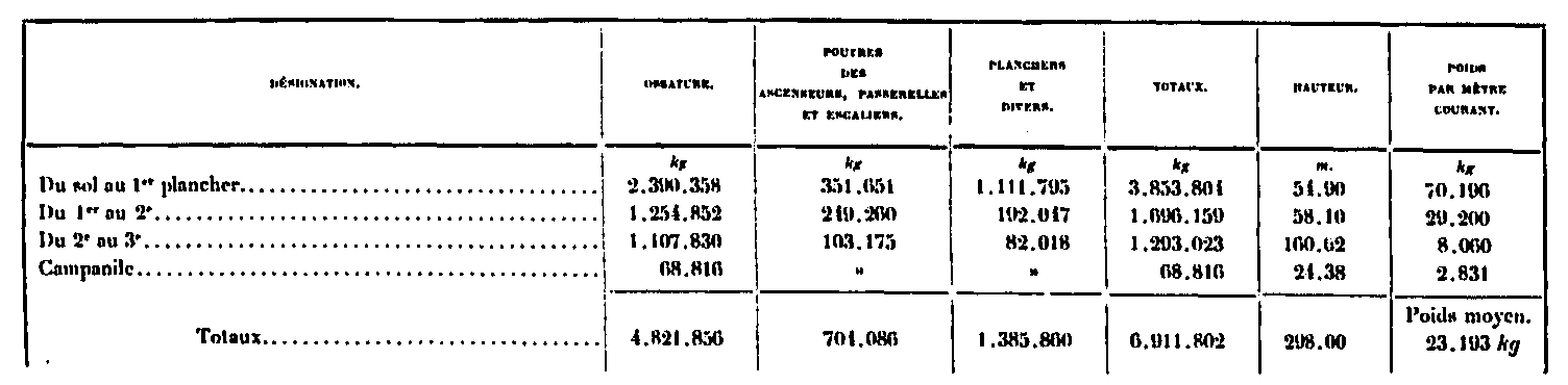
Metallic superstructure proper: 6 911 802 Kg
Total : 7 341 214 Kg
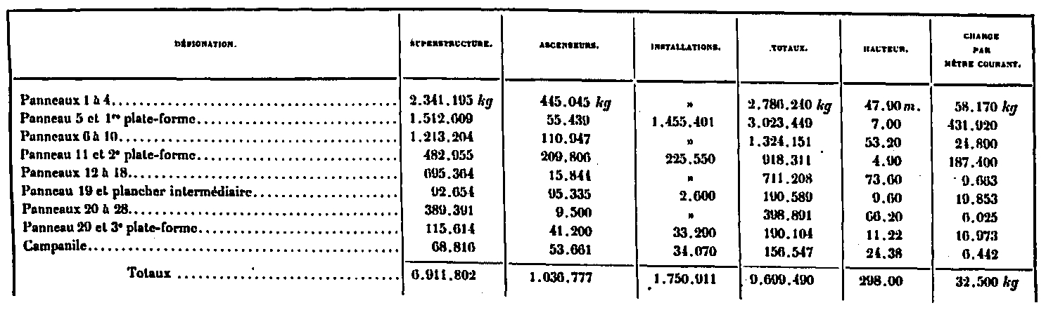
The weight of the superstructure itself is broken down as follows:
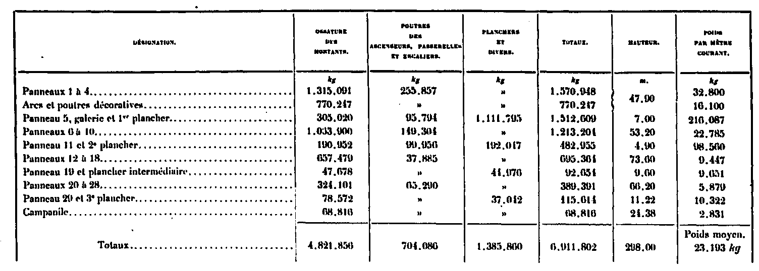
The figures in this table are summarized in the following:
The weights which, apart from the metal superstructure proper, will have to be included in the calculations, are those of the mechanisms and accessories of the elevators, as well as those of the buildings and the subsoil of the platforms. We will study them separately.
2. Lifts
They have the following weights, which will be detailed in the chapter that will be devoted to them:
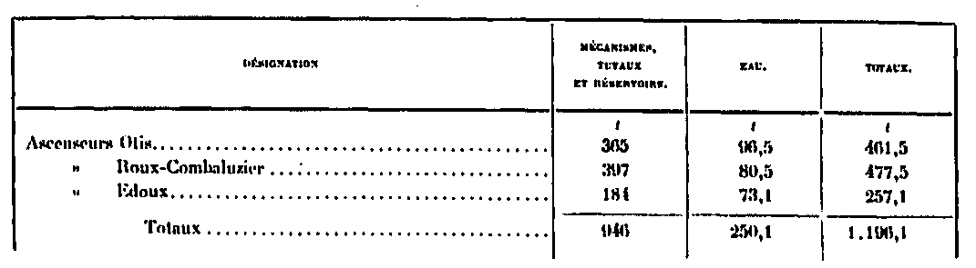
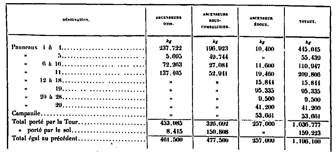
By analyzing the distribution of these various loads according to the different parts of the Tower, we arrive at the table below:
3. Various installations and platforms
a. In the campanile, the pavilion comprises:
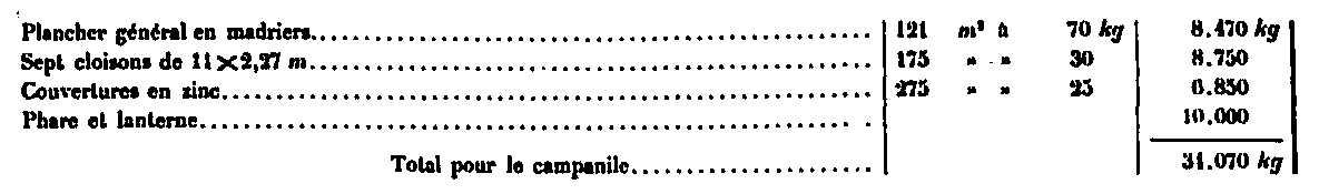
b. In panel 29 and the third floor, it is necessary to count:
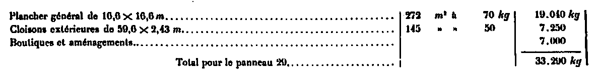
c. In panel 19 and the intermediate floor, only the floor and bulkheads of the machinist's room, whose weight is 2,600 kg, shall be counted
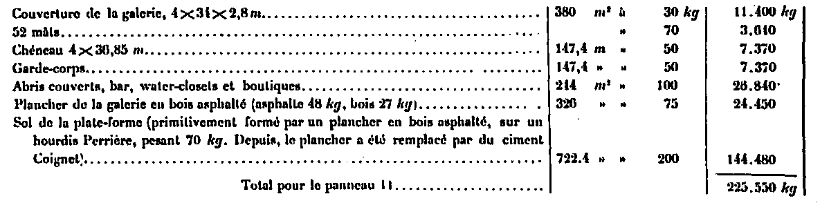
d. For panel 11 and the second platform we will take:
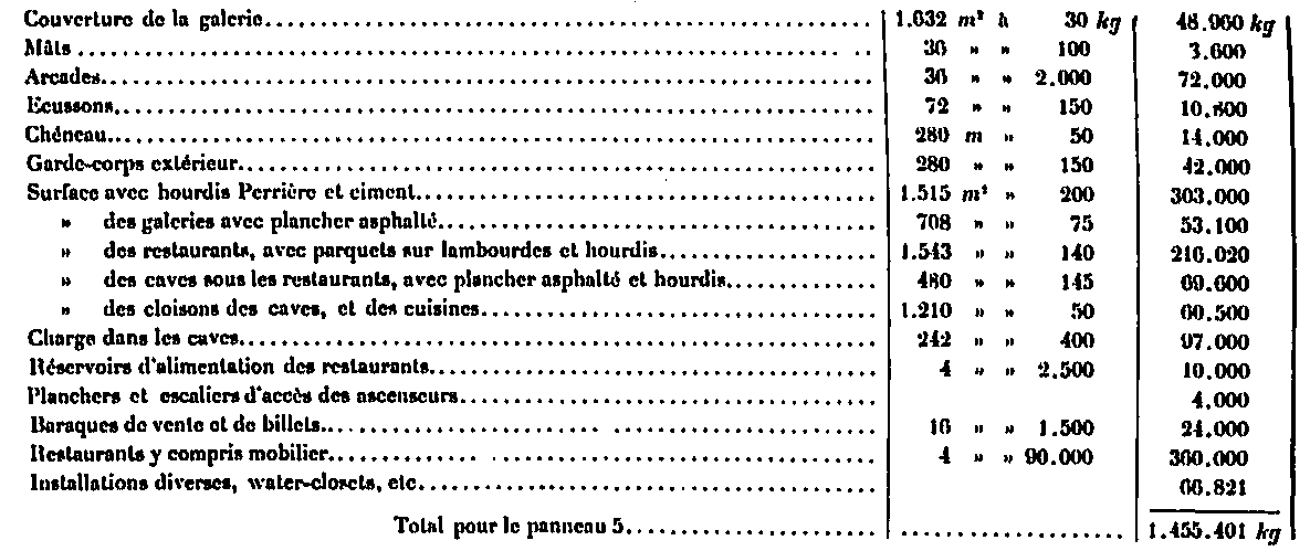
e. In panel 5 and the first platform, are the most important weights:
The charges due to various installations and platforms, are therefore:
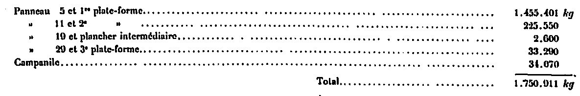
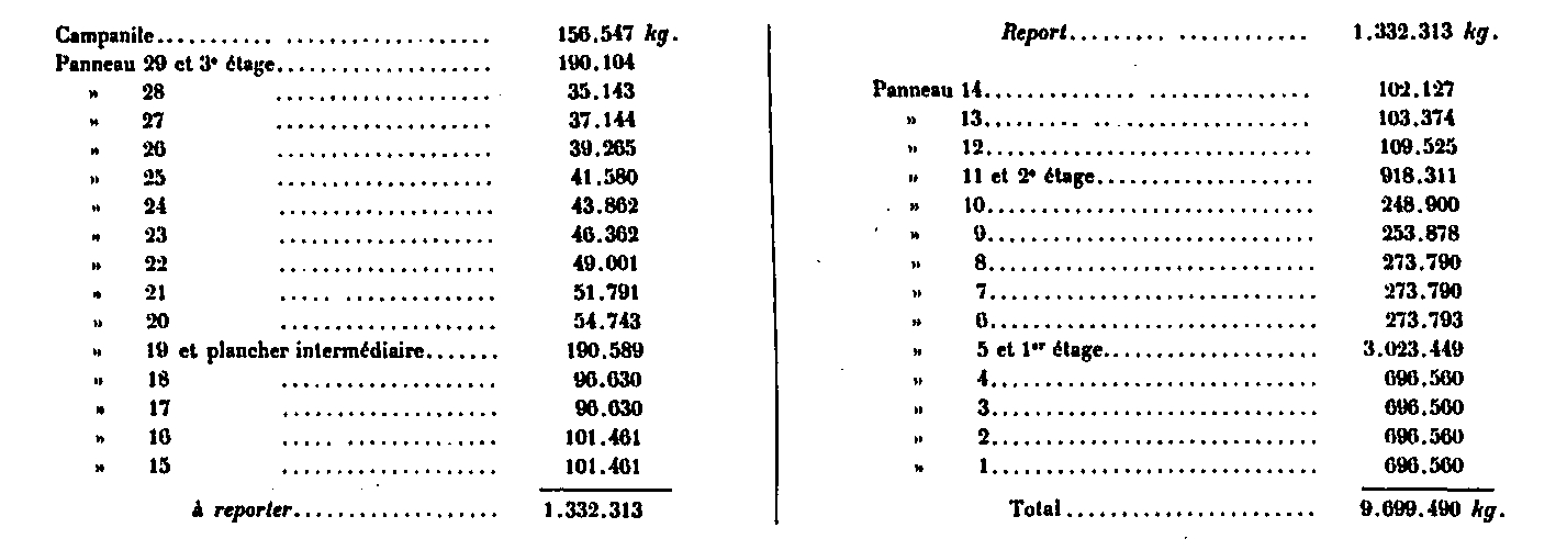
The set of vertical loads acting in the different panels is summarized in the following table:
This load of 9,700 tons, which is the total weight of the Tower, is the one adopted in the calculations. The weight of unspecified intermediate panels is deduced from their height, and the weight per corresponding current metric.
Could the tower have been higher?
This chapter answers this question by considering the addition of the weight that would represent an additional elevation of the tower. If we take, in the preceding tables, the weight of the frame alone, that is to say the weight of the uprights and that of the belt girders, after deduction of the floors and the beams of the elevators, these weights are the following:
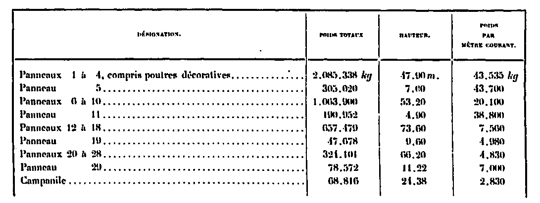
The weights of the metal superstructure, given previously, can be summarized in the diagram opposite, in which the chopped parts represent the quantities of metal used in the Tower. The curve in solid lines refers to the weights per running meter, relating to the construction as a whole. That in dashed lines is relative to the frame of the uprights, including the girders of the belts, after deduction of the floors and the elevators.

Forces of the Eiffel Tower
Forces of the Eiffel Tower

Forces of the Eiffel Tower
We see that these weights increase very rapidly with height. We can induce what would have been the approximate weight of the Tower if it had been extended by 50 m, that is to say if it had been given a height of 350 m.
The weight of the panels 1 to 4, without the decorative beams, and for a height of 47 m from the supports, is 1 315 091 kg, ie by current meter 27 500 kg. That of the panels 6 to 10 is, for a height of 53.20 m of 1 063 900 kg, or per meter current 20 100 kg. It follows that if the tower had a height of 50 m more, that is to say, if we had adapted to the lower part a floor of 50 m, the width at the base would have been 150 m about, and the weight of this floor would have been, as frame of the amounts, 35 000 kg per meter current approximately. The corresponding additional weight is 35,000 x 50 = 1,750,000 kg.
As for the weight of the new girders of the belts and the panel at this new height, it would have been 43700 x 100/53, that is to say 82 500 Kgl which, for a height of 10m gives 825 000 Kg, not including the floors , elevators, etc. The total weight of the superadded stage would therefore have been at least 1,750,000 + 825,000 = 2,575,000 kg. The comparative weight of the construction is that of the framework of the uprights (4,821,856 Kg) less that of the decorative beams (77,247 Kg), or 4,051,609 Kg. Thus, for a height increase of 50/300 = 17 %, the weight would increase by 2,575,000 / 4,051,000, or 63.5%!
Thus calculated, it seems obvious that the tower should not be raised beyond the 300m, except to have the capacity to increase the expenditure by about 3 million francs at the time, according to a estimate by Gustave Eiffel.
Vertical loads acting in sections
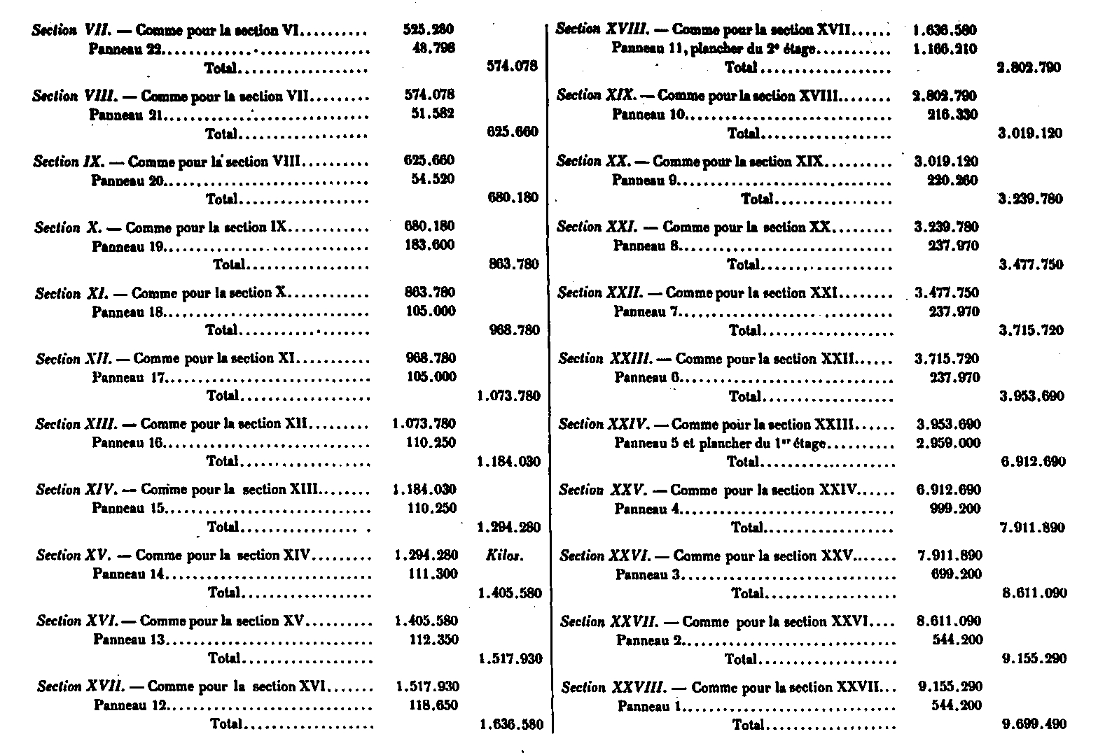
From the foregoing tables, the load due to each of the panels can be deduced by applying, in proportion to their height, the load per current meter relative to the various categories admitted. These charges are as follows:
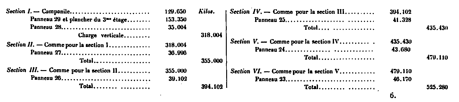
Although the calculations of the Tower were made with the total weight above, differences in the distribution of loads, especially with regard to the elevators, had led to slightly different figures for the loads in each section. Nevertheless, we have found it quite useless, in view of these differences, to make these arduous calculations again, for the reason that these partial differences have no appreciable influence on the value of the coefficients of labor. They are by themselves only of importance in the upper part of the Tower. Now, it will be seen later that in this part the influence of the wind is very much predominant over that of the charges; moreover, in the panels 12, 13 and 14, where the total coefficient of work is quite high, the influence of the reported differences can be considered as absolutely zero.
We can therefore, without any inconvenience, keep the following charges originally adopted for each of the 28 sections; each of these loads is obtained by summing the weights of the panels situated above the considered section.
Calculation of the upper part
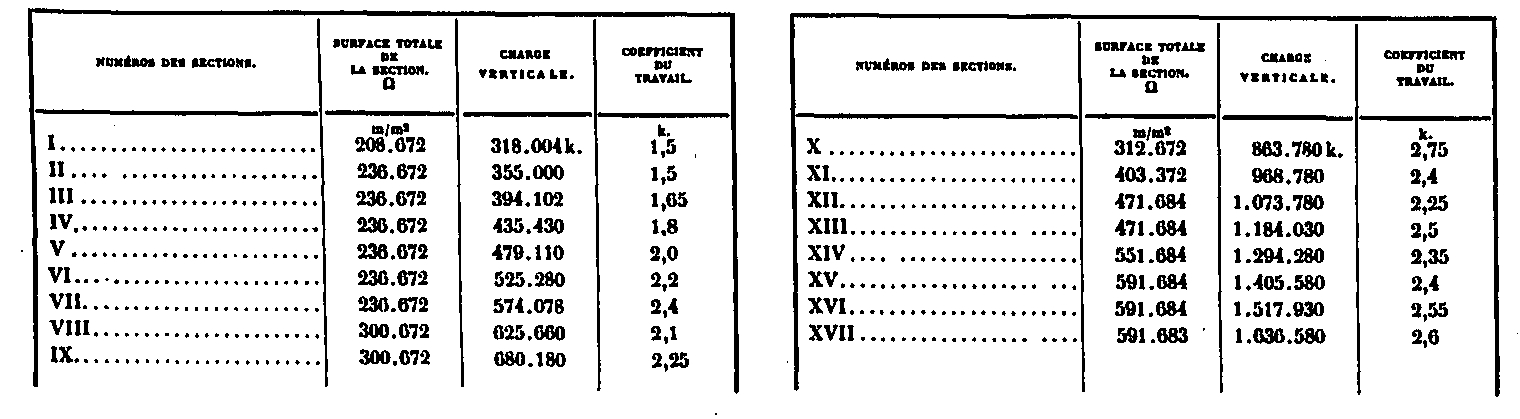
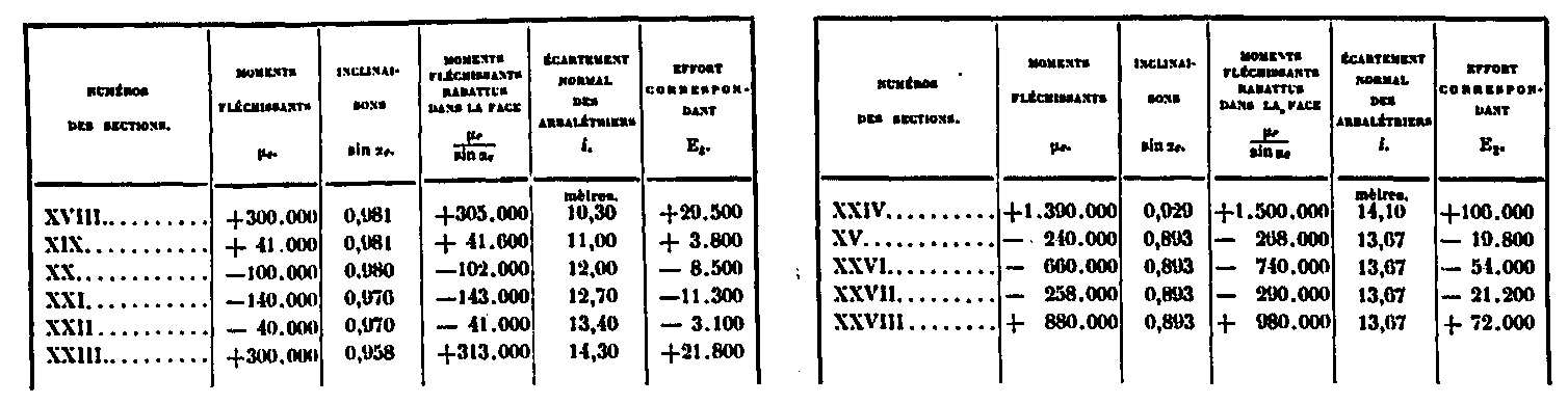
In the upper part, above the second floor, the rafters are almost vertical and the influence of their inclination is insensitive. We obtain directly the coefficient of work R by dividing the total effort P of the loads situated above the section considered by the total surface a of all the crossbowmen cut, that is to say that one has R = ~. The following table summarizes these efforts, which vary from 1K, 5 to 2K, 6, thus leaving the necessary margin for wind resistance, which has a preponderant effect in this part of the Tower
Calculation of the lower part (Method used)
We will calculate for each amount taken in isolation. The total weights of the various panels of the Tower which we determined above P1, P2, ... are distributed equally between these 4 amounts: the weights of which we we will use in our calculations, are the weights P1 = P1 / 4, P2 = P 2 / 4, etc. applied to the centers of figure of the panels, centers whose assembly constitutes the average fiber. The force outside a section is the result of all vertical loads and horizontal forces acting above the section. The vertical component of this force is equal to the loads; the horizontal component results from the action of the belts at the 1st and 2nd platforms. We will first calculate as if the system were articulated at the points α, β, meeting points of the belts with the average fiber (Figure 1).
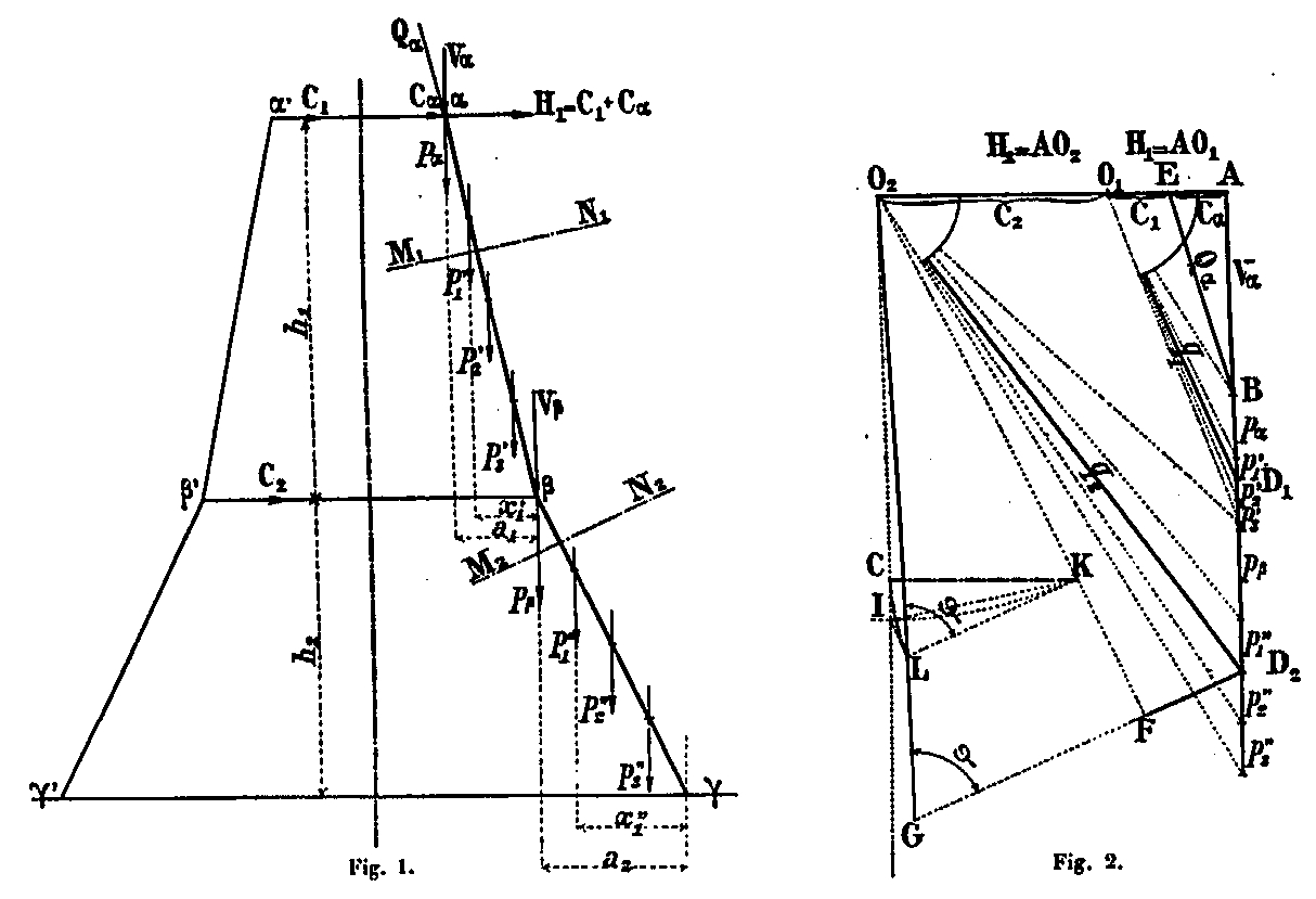
Let Qα be the resultant forces acting on the amount above the α α it passes, according to the accepted hypothesis, by the point α of the middle fiber and is in the direction of the element above the belt.
- Vα and Cα, its vertical and horizontal components.
- ρα = Pα / 4, one quarter of the total weight of the floor of the 2nd floor located on the belt αα'.
- C, the effort in the belt αα'.
- a, the horizontal spacing of the points αβ.
- x1', x2', x3',... the horizontal distances of the point β at the points of application of the charges ρ1', ρ2', ρ3' acting on the amount between the two belts.
- h, the distance of belts α et β
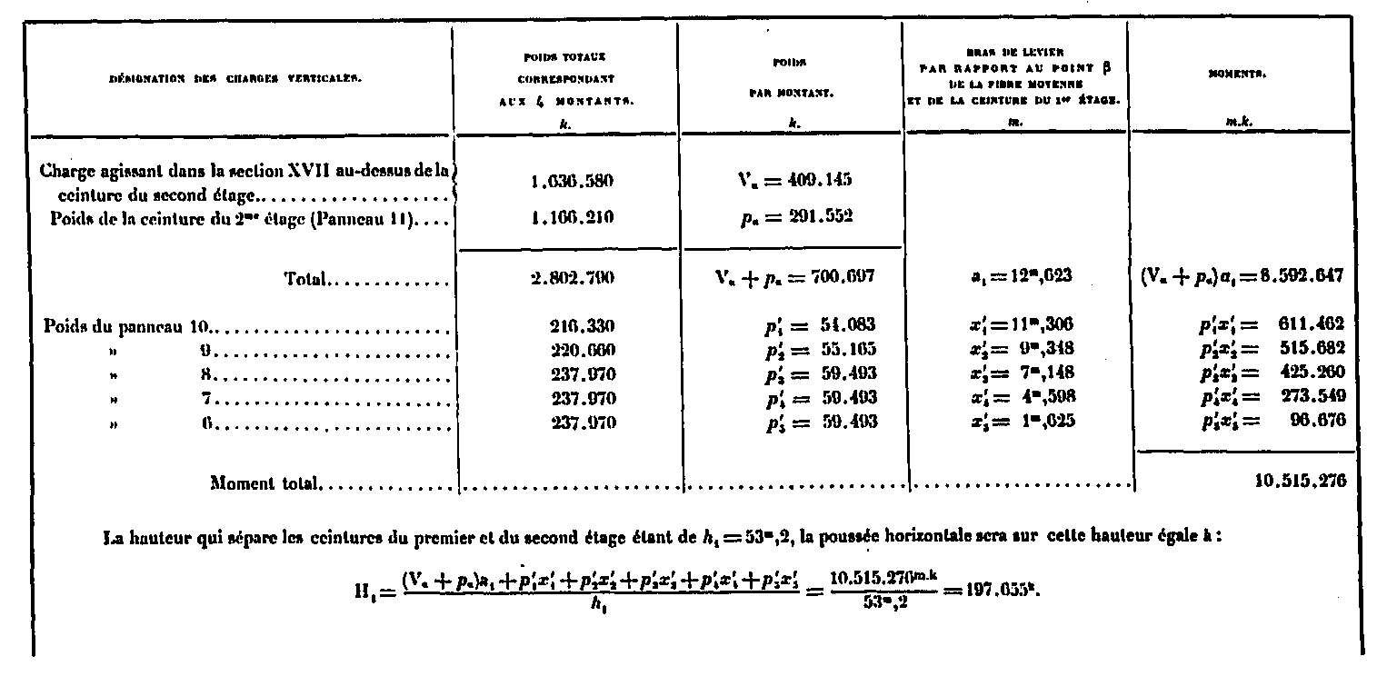
- H1, the resultant horizontal forces acting at α and whose value is H1 = Cα + C1. To have the value of H1, just like the amount αβ is in equilibrium, to equal the moment of the external vertical forces with respect to the point β, to that of the horizontal resultant taken with respect to this same point, which gives H1ρ1 = (Vα + ρα) a1 + ρ1'x1' + ρ2'x2' + ... from where we conclude H1 =1/ρ1 [(Vα + ρα) a1 + ρ1'x1' + ρ2'x2' + ...], expression in which all elements are known.
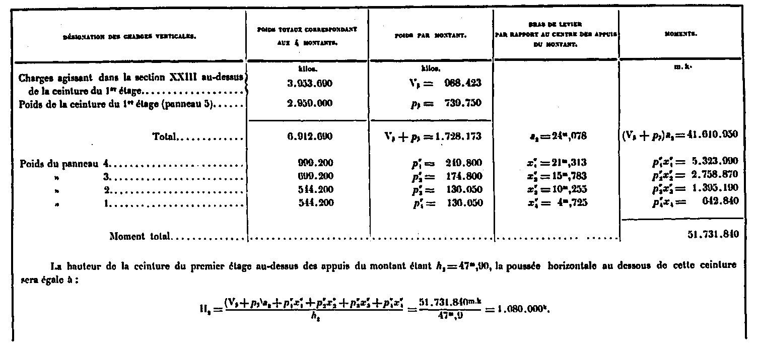
We would have the same for the part βϒ = 1/ρ2 [(Vβρβ)a2 + ρ1'x1' + ρ2'x2' +...] with Vβ representing the sum of all vertical forces acting above the waist ββ'.
- ρβ a quarter of the weight of the floor of the 1st floor located on the beltββ'.
- ρ1", ρ2", etc. the charges on the amount below the belt ββ'.
- x1', x2', x3',... their leverage relative to the point ϒ
- a2 the horizontal spacing of the points β and ϒ.
- ρ2 the spacing of the belts β et ϒ
Knowing H1 and H2, we can build the force polygons, one of which, polar distance AO1 = H1 will apply to the part αβ, the other, polar distance AO 2 = H 2, to the β (Fig 2).
For any section M1N1 between the belts αα'; et ββ', the external force is given by the radius O2D2, which starts from the pole O2, and go through the point D1 separation of forces ρ1 et ρ2 between which is the section M1N1.
For a section M2N2, made below the belt ββ' the external force is given by the radius O2D2 which starts from the pole O2 and ends at the point D2, located between the forces ρ1" and ρ2".
The distance of the poles O1 and O2 is equal to the compression force C2 of the belt ββ' which is H 2 - H 1.
As for the forces Cα and 1 the first is determined by leading by the end B of the line AB = Vα a parallel to the element above the belt: AE is this force. As a result O 1 E is the force C1 ad = Qα.
Having the external forces such that q1 q2 one will obtain the compressive forces and the shear forces by decomposing each of them in two forces: the one parallel to the average fiber in the considered section and the other normal in this direction. The compression force thus obtained is that which acts in the vertical plane, it must be brought back into the plane of the amount and decomposed according to the inclination of the amount in folding.
This decomposition is shown in the figure for the external force q 2 = O2 D2 of section M2 N2; we first obtain, by drawing the line O2 F parallel to the average fiber and lowering the perpendicular D2 F, a shearing force D2 F and a compressive force O2 F acting in the vertical plane. To bring it back to the plane of the face, the folding is done as follows (Fig. 3):
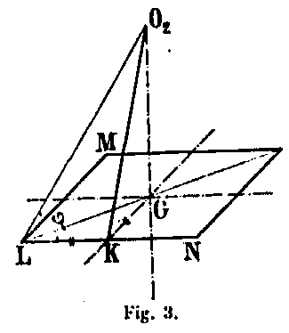
From the pole O2 as center we draw an arc from the point I located on the vertical of the pole to the point K on O2 F. From point K we raise a perpendicular KL to O2 F and from point I a perpendicular IL to KL. Point L is the intersection of these two lines. O2 L is the desired direction of the force in the plane of the amount. Indeed: MN being a horizontal plane, to have O2 L knowing O2 K, it suffices to have the length KL = KC and to bring it to a perpendicular at O2 K high at point K. To have KC it is necessary to lower from point K a perpendicular to the vertical O2 C. By reducing the length obtained on the direction KL, we have the point L sought that can also be obtained by the construction indicated in the sketch (Fig. 2), because in the triangle ILK obtained by leading the perpendiculars KL and IL, we have KL = KC. By projecting the force O2 F normally to its direction in the direction O2 L, we finally obtain the force O2 G which is the real compression effort of the amount. This force N gives, in each of the 4 crossbowmen, a, b, c, d of the amount, a force E, = N2 / 4.
As for the shear force F2, it will be carried on a line normal to the average fiber and decomposed in the direction of the corresponding lattice bars, which will give the effort in each of them for the set of two faces. In reality, the system we studied is not articulated, it is on the contrary embedded in the base ϒ as well as points α, β as a result of the continuity of the amount, and we will take into account this continuity in the calculation of the bending moments due to the inclination of the uprights and the action of the vertical loads acting against the points of support that form the belts.
We will first notice that the first hypothesis which has been used for the determination of the forces does not change in any way the absolute value of the compression forces and the real shear forces: it corresponds only to a displacement of the curve of the real pressures parallel to it. -even. The curve of the real pressures can be traced with the same polygon of forces as that fig. 2.
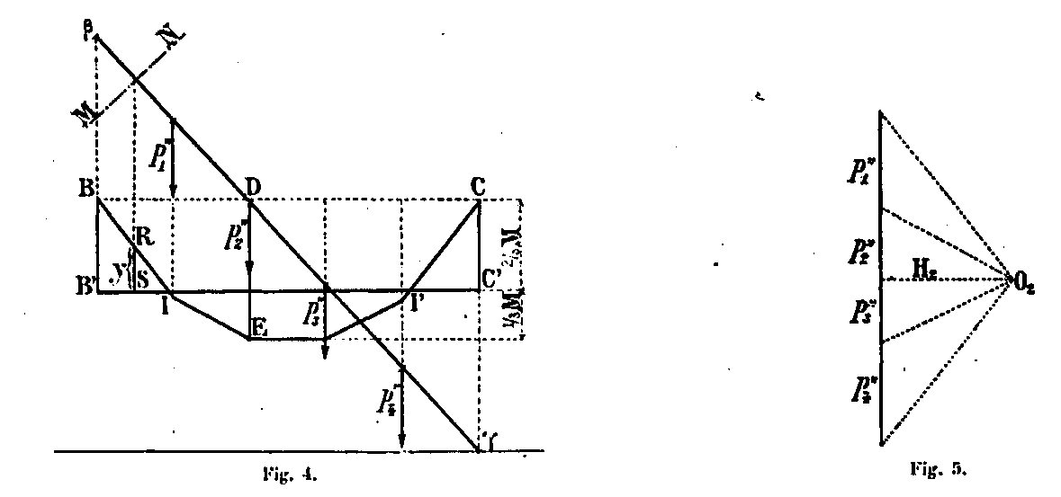
Considering the βϒ part, we can draw the funicular polygon BEC (Fig. 4) corresponding to the force polygon ρ1'2' ρ3' which act on the βϒ part. It is known on the other hand that if M is the maximum moment of a beam uniformly loaded and resting freely on its supports, the moments of the same beam embedded at each of its ends are:
2/3 M on the supports and 1/3 M in the middle of the span. According to our hypothesis of embedding, we have in β and ϒ moments of embedding BB '- CC' equal to 2/3 of the maximum moment DE, which would occur if the amount was articulated in β and ϒ. The moments are represented at any point by the ordinates of the funicular polygon measured from the line B'C parallel to BC and vertically distant from it by 2/3 of the moment DE. They are positive in parts B'I and I'C 'and are negative between points I and I'. For a section MN, the moment is equal to μ = RS x H 2 ϒ H 2.
One will calculate in the same way the bending moments due to the self-weight in the part αβ the amount between the second and the first platform. The moment thus determined acts in the vertical plane XY. It is produced by the slope α1 of the projection of the amount on this plane. We also have in the vertical plane UZ, perpendicular to XY, a moment which is due to the inclination of the upright in the direction UZ. Since the angles α1, being the same in both XY and UZ directions, these two moments are equal. To obtain the corresponding pairs which act in the faces of the upright, it is necessary to decompose these two pairs μ following the inclination of the faces. Let RS be the axis representative of the moment μ1 in the plane XY, R'S ', the representative axis of this same moment in the plane UZ. To compose them, we will decompose each of them according to the vertical and following a normal to the average free, ST and RT = μ1 / sin α, S'T' et R'T' = μ1 / sin α. The vertical components ST, S'T 'being equal and of opposite sign cancel each other out; the normal components RT, R'T 'remain alone.
The moment RT produces in the walls ab and dc, for positive values of the moment, a compression force on the rafters a and d and a tension in the rafters b and c. Similarly the moment R'T ', in the vertical plane UZ, produces in the walls ad and bc a compressive force for the rafters a and b and a tension for the rafters d and c.
Designating by E ', the effort in the crossbowmen, and i, their spacing, μ1 / sin α1 being the moment relative to the set of two faces ab and dc, we have for one of them E'i = (I/2) x (μ1 / sin α1) d where E '= (I/2i) x (μ1 / sin α1). This effort E' gives a compression on the rafters a and d and a tension on the rafters b and c. We would have the same for the faces ad and bc, the effort E" = (I/2i) x (μ1 / sin α1) which gives a compression on the rafters a and b and a tension on the rafters d and c.
The total compression effort will be: for the crossbow to E2 = μ1 / (i sin α1) and the total tension forces: for the crossbower c E2 = μ1 / (i sin α1). For the rafters b and d, the efforts are canceled. The total forces produced in the rafters of the lower part by the effect of the vertical loads, taking into account the bending moments is thus
- for the a crossbowman has an effort to Ea = E1 + E2
- for the c crossbowman has an effort to Ec = E1 - E2
- for the b crossbowman has an effort to de Eb, d = E1
Bottom section (Numerical calculations)
We must first determine the values of H1, and H2, that is to say the horizontal forces acting on the right of the belts. The tables below give the calculations.
Calculation of the horizontal thrust H, due to the vertical loads between the first and second stage belts
Calculation of the horizontal thrust H2 due to vertical loads below the belt ββ' first floor
These values which are on each of the amounts, on the second platform: 197 655Kg, at the first platform 1 080 000Kg, make it possible to establish the polygons of the forces of figure 6 of the board XXXII, according to the method given above, for the figure 2. One deduces all the values of N2, compressive force of the amount and consequently E1 = N / 4, compressive force of each of the crossbowmen. The value of shear forces such as D2 F of the same figure is also used. These values are listed in the table below:
As for the efforts in the crossbowmen due to the bending moments, we saw that they were represented by the expression E2 = μ / (i sin α1) wherein:
- i is the normal spacing of the crossbowmen
- α1 the angle of inclination on the horizontal of the projection of the average fiber on the vertical plane
- μ1, the ordinates with respect to B'C (see Fig. 4) of the funicular polygons constructed with the polygons of the vertical forces between α and β and between β and ϒ.
These polygons are represented in figures 4 and 8 of the board XXXII. The polar distance was taken from 100,000K. The scale of lengths being 0m, 003 per meter, the scale of the moments will be 0m, 003 per 100 000 m. K.
We thus arrive at the following table:
The total forces on each of the crossbowmen, as well as the working coefficients, are given in the table below:
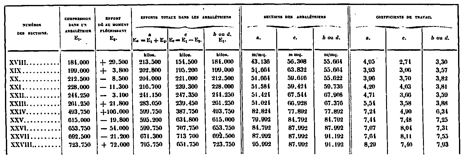
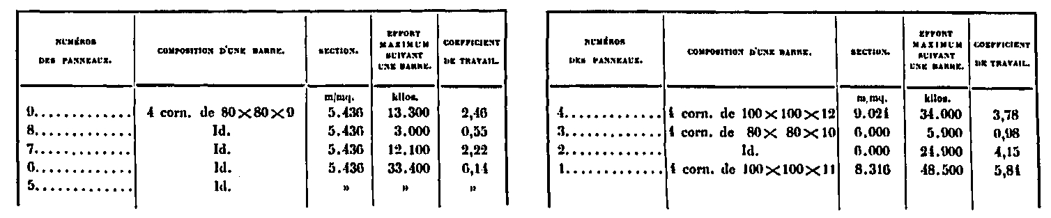
As for the lattice bars, their working coefficients are given by the following table:
These are the effects of the weight of the construction of the Eiffel Tower. You have the calculations for the wind resistance on this page.
See also: