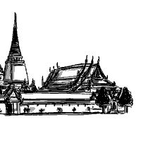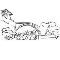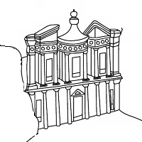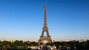

The Eiffel Tower was built in Paris between 1887 and 1889, a time during which the industry was booming. But once finished it was necessary to maintain it, and to maintain a building as important as that it was not easy. Yet it was done regularly, and that's why we still have this tower, right in Paris.
Aside from the almost daily changes, the tower has undergone several major renovations. The first in 1900, on the occasion of the universal exhibition of 1900, the next in 1937 for the equivalent of a world exhibition, it was called "the international exhibition of Arts and Applied Techniques to Modern Life" ". The next renovation took place only during the 1980s, but it was important. Finally the last renovation dates from 2011.
Improvements of 1890
The Paris Universal Exhibition, which ended on October 31, 1889, saw many visitors climb the Eiffel Tower. With this experience, Gustave Eiffel decided a few small adjustments, sometimes to smooth the circulation on the monument, sometimes to remove the pavilions proper to the exhibition and therefore no longer needed.
The tower was closed for the first time between November 1889 and the spring of 1890 to make these changes there, of which we have few traces. But it is especially 10 years later that the first real restoration of the monument arrived, before the following ones.
Renovations of 1900
The renovation of 1900 is probably the most important of all, but nowadays we do not necessarily realize it because it is old. Yet that year Gustave Eiffel made many changes in turn to make it more modern, more convenient for visitors. It must be said that technology had taken a big step in about ten years, we were at a time when every day brought its share of novelties, construction techniques, knowledge. The chance we have is that the tower was still under the concession of its designer, so it is Gustave Eiffel himself who undertook this renovation and found the trace of all the modifications undertaken in his work, written after the universal exposition of 1900 in his book "The tower of 300m".
These changes concern two functions:
- Increasing the useable floor space on platforms,
- Elevator upgrades to increase visitor flow
There are therefore two major parts to the 1900 changes, one describing the arrangements of the first, the second and the third platform, the other describing the general layout of elevators, the new Fives-Lilles Otis lift from the North Pillar, from the vertical elevator at the top, stairs, machines and boilers and finally electric lighting.
Since the surface of the first platform could not be enlarged, at that time it was better to use the existing surface better to improve the circulation of the public. In particular, the passage that existed between the back of the restaurants and the inner railing of the platform's central void was much too narrow for significant traffic to occur. In addition, these posterior facades had been treated too simply, they were rather unsightly. Suddenly this part of the platform was almost unused. Consequently, it was decided during these improvements to increase this interior passage to a minimum width of 2 m, thus reducing the rear façades of the buildings. At the same time, the aim was to give them a more lively and lively character by giving them a livelier silhouette and by setting up shops and bars. This new ornamentation was made in harmony with the character of each building and is represented in the board XLVII.
This widening of the free passage and the location of these shops were largely in the terrace extensions to the offices and ancillary services. These offices were retreated indoors by encroaching on the consumer area, which is reduced to two farm spacings on all three spans. But this decrease was more apparent than real and affected only very few of the places actually occupied by the public.
Figures 1 to 6 of board XLVII indicate the new arrangement adopted for restaurants English, Dutch and Russian. The detail of the plan of this facade is given in figure 2 of this same plate. As for the French restaurant, there were no other modifications than the change of decoration of the facade and the suppression of the two small reserved lounges which made obscure and almost useless the greater part of the corresponding span.
The changes were much larger on this platform than on the first one. Indeed, during the 1889 Exhibition, it was particularly crowded, not only because of the location necessary for the change of elevators inclined to the vertical elevator, and for the formation of the tails that were the consequence, but also by the existence of unused extensions of the Elevators Combaluzier paths and by that of the large cylindrical tanks supplying the lifts.
As this platform is one of the most pleasing of the Tower, it was decided to give it the greatest possible attraction for the visitors, and the lower surface was first enlarged by a strip around the 2 m wide, and a second floor terrace was built on part of its surface; finally, all the little kiosks that were scattered on the platform were united in a single central pavilion.
But that resulted in a noticeable increase in the weight of the platform that would not have been without inconvenience. The essential condition of this transformation was the removal of cylindrical tanks so bulky, feeding lifts and whose weight, full of water, exceeded 100 tons.
This is how we were led to feed the elevators accessing this platform by a system of accumulators resting on the ground, and also to remove the Perrière slab, as will be explained a little below, in this page. The first modification consisted of removing the covered gallery from the perimeter and increasing the protrusion of the consoles bearing the floor by 2 m. For this purpose, new consoles made of solid plate were applied in front of the old ones, according to the layout shown in figure 3 of the board XLVI. This created an open platform 4 m wide, ensuring a wide and pleasant outdoor circulation.
A second modification, consisting of the construction of a terrace, was also realized. On the inside of the large belt girders, at each 3.36 m interval, stands an iron pillar of 3,312 m in height, supporting at this level a balcony projecting 0.70 m and provided on its outside rim of a slight balustrade. At the rear of this balcony projecting from the external faces of the crossbowmen of the Tower, the floor, supported by two new iron pillars, extends to the central pavilion on a width of 8 m. The three pillars are connected by a 0.25 m high spacer to which the 160 x 90 double-T joists spaced 1.10 m apart are attached. On these joists are riveted sheets of 3.5 mm thick stiffened by 40 mm angles. These sheets will be covered by linoleum and will form a 8.90 m wide walkway. All these provisions are shown in Figures 1 and 2 of the board XLVI.
This floor, inclined to the outside to allow the flow of rainwater, enclosed inside an octagonal space of 16.35 m wide and 6.725 m side, assigned to the central pavilion. It does not touch the location of the elevators East and West and communicates with the floor of the platform by eight stairs, placed in the neighborhood of the pillars. The central pavilion, represented in figures 7 to 10 of the board XLVII, includes a ground floor and a first floor. The outer pillars of this pavilion are of wood. The floors and the frame are made of iron; pavements, ceilings, interior partitions and facade fillings are made of expanded metal plaster.
On the ground floor are installed: the cage of the vertical elevator, with its entrance and exit at the platform, a bar and its office, three shops, toilets, the ticket office , as well as access stairs to the first floor. Below, there is a cellar. The part of the floor of the terrace that surrounds this pavilion serves as shelter for walkers in case of bad weather. The shops are illuminated by the day coming from the upper floor through slab-glasses.
The first floor also includes the elevator shaft with its entrance and exit at the terrace, an administration office and finally the restaurant rooms accessed by a few steps. On the ground floor and between the main beams of the central elevator is installed a sheet tank of 30 m3 of capacity, serving to feed the Otis elevator kept at the North Pillar.
As for the tessellation, we have seen that the Perrière slab, which was originally covered with an asphalt wood floor, was later reinforced with cement slabs (Coignet system); the weight of this pavement including hourdis was 145 kg. In the current construction, the Perrière slab is removed, and the pavement is made only by rectangular slabs of reinforced concrete that rely on the joisting through wooden rafters. These slabs, which all arrived ready to the site, have a weight of only 70 kg per square meter. Their dimensions are: length 1.35 m, width 0.67 m, thickness 0.030 m. They are provided at their perimeter projecting rims 60 mm thick, to facilitate their support on the joist. Between the seals is placed rubber to allow the expansion to occur, while sealing.
It is thanks to these various modifications that the total weight of the platform remained what it was previously.
There is no change in the lower part of the third platform, except that in partition walls the wood is replaced by expanded metal.
The upper gallery, which Gustave Eiffel had until now reserved, is delivered to the public. Its floor has been consolidated accordingly and the wood has been replaced by sheet metal.
The distribution is modified to give access to the Imperial over the cabin of the vertical lift. In addition, some shops have been installed around the perimeter, and the facades have received a new decoration, replacing as much as possible the wood with expanded metal hoarded, so as to rule out any chance of fire. All these provisions are represented in figures 6, 7 and 12 to 15 of the board XLVI.
Finally, it was installed above the large cross beams of the campanile a small pavilion reserved for Eiffel. This glazed pavilion is made of sheet metal and of hexagonal shape; it is 5 m wide and 2.12 m wide. It is accessed by a staircase from the upper gallery. This flag is represented in FIGS. 9 to 11, board XLVI.
The previous situation of lifts
With a view to increasing the number of passengers on different platforms for the 1900 Exhibition, the Society of the Tower decided to modify completely the system of the elevators accessing the first and second floors. Before indicating these modifications, it is necessary to recall what was in 1889 the practical yield in travelers, mounted by the various elevators of the Tower.
1. Otis lifts. During most of the Exposition, one of the Otis elevators was in direct service on the second floor, raising an average of 37 people per hour, 9 trips and 42 travelers, or 3,780 in the day 10 hours. The other elevator served first to second, and during the 10-hour day, 12 trips of 42 people per hour, 5,040 passengers from one to the other floor. Under these conditions, the number of passengers carried during the day from 10 am to the second was 9000 people.
Note that with a service organized so that one of the Otis went from the ground to the second with a stop at the first to exchange travelers, he made only 7 trips per hour, and the number travelers was 7 x 42 x 10 or 3000, either from the ground to the first, or from the first to the second; this mode of operation was less advantageous. In short, Otis elevators could raise up to 9000 passengers per day by 10 hours on the second platform.
2. Combaluzier lifts. Each of these elevators specially assigned to ground service on the first floor could raise between these two levels, at the rate of 10 journeys per hour and 90 passengers per ascent, a number of 9000 persons during the day of 10 hours, or 18000 for both devices in the same system.
3. Vertical lift. The practical hourly performance of this elevator, serving second to third, included 7 trips of 65 people, or at most 4,550 passengers in 10 hours.
4. Total yield. The number of passengers traveling to the various platforms and the corresponding revenues, according to the normal tariff, were as follows:
- At the 1st platform (Combaluzier lift): 18000 to 2 francs = 36 000 francs
- At the 2nd platform (Otis direct): 3800 to 3 francs, or 11 400 francs
- At the 2nd platform (Otis from 1st to 2nd): 5000 to 1 franc, or 5,000 francs
- At the 3rd platform (Edoux): 4550 to 2 francs, or 9100 francs
- Total : 61 500 francs
This recipe was almost completed on September 9, which produced a figure of 60 756 francs, including stairs. The maximum number of visitors was 23,202 on June 10, a busy day. It must be said that it was the Monday of Pentecost.
General improvements
The changes that were projected for the 1900 Exhibition are as follows:
1. First and second floor service. The two lifts of the Roux, Combaluzier and Lepape system are replaced, at the East and West pillars, by two high-powered lifts, built by the Compagnie de Fives-Lille for the service of the first and second floors. These lifts will allow, with stop to the first, to make 10 trips per hour, raising per trip 100 persons minimum, half of which will directly travel to the second platform and the other half will stop at first to go back to the second platform to a next trip; that is to say, if the cabins were still full, the number of passengers going up to the second would be 20,000 with or without stops, and the total revenue, with the normal rate of 3 francs, would be 60,000 francs.
In addition, the Otis elevator installed in the North Pillar will only do soil service on the first floor. It is transformed so that its speed makes it possible to make 14 journeys by the hour with 80 passengers, which allows to transport in 10 hours 14 x 80 x 10 = 11 200 people, which, for the price of 2 francs, give rise to a recipe of 22,400 francs. The revenue figure for the three lifts is therefore 60,000 + 22,000 = 82,400 francs. This figure, compared to that of 36,000 + 11,400 + 5,000 = 52,400 francs, gives a daily increase of 30,000 francs, or 57 per cent. These figures are a measure of the increase in the potential yield of new elevators for the first and second floors.
The elevator of the South pillar is removed and in its place is installed a wide staircase used to perform descents from the first floor; the two existing staircases at the East and West piers will be assigned solely to the ascent, and this service will be doubled relative to what existed in 1889. In addition, the four small spiral staircases, from the first to the second, whose use was not practical, will be replaced by a large single staircase located in the South stack in extension of the new staircase. The performance of these stairs can be very important. Existing stairs have often delivered 1,500 people per hour. The new ones could therefore give 3,000 people per hour on the first platform and 1,500 per second. But these maxima can be realized only during a few hours of the afternoon, during the days of great affluence. They can not be included in the calculations except to supplement the maximum flow rates of the elevators mentioned above.
2. Second to third service. The vertical lift does not receive any essential modifications. We are satisfied for the daily service of the day to provide an imperial discovery that can accommodate 25 people. The cabin itself will only receive 55 people, a total of 80; it was this number that was sometimes admitted, but with a stack of travelers very uncomfortable and giving rise to great delays for entry and exit. By distributing them differently, there will be any advantage and the trip will be more enjoyable and faster. During the first and last trips, while the cabins ascending and descending are insufficiently balanced, access to the Imperial will be removed and the number of passengers per cabin will not exceed 60. With some modifications of detail in the distribution that will be improved in order to reduce the pressure drops and to increase the speed, and in the doors which will be widened, one can hope to make 10 journeys by the hour. We would thus climb in 10 hours, if we are not spared by congestion, a number of 80 x 10 x 10 = 8 000 passengers, giving a new recipe of 8000 x 2 = 16 000 francs which, added to the previous receipt of 82,000 francs, provided a total income of 98,400 francs.
This figure, compared to 61,500 francs for the old installation, gives a daily income supplement of 36,900 francs, or 60%. These numbers are a measure of the benefit of the new elevator installation.
It is with the idea that the second platform itself will be three times more frequent than in 1889 when its surface has been much increased and uncluttered.
Replacement of Roux-Combaluzier lifts
The Roux-Combaluzier-Lepape elevators that had been installed in the North and South Pillars in 1889 were no longer efficient enough to manage the flow of visitors to the future World Expo of 1900, also Gustave Eiffel chooses to replace them with elevators of the brand Fives-Lille, more efficient. All that is possible to know about these lifts is described on the page dedicated to them: Description of Fives-Lille lifts.
The Roux-Combaluzier-Lepape elevators were simply destroyed.
Otis Elevator Changes
As the ground run on the 1st floor is about half of the total stroke, it becomes possible in 1900, for the same stroke of the engine piston, to muffle the 7-strand moving carriage instead of 12 and to increase in the same ratio charges it to raise. The frame of the pulleys of the 2nd platform was lowered to the 1st. As for the pulleys themselves, those which receive the traction cables are replaced by pulleys 3 m in diameter of the kind used by the Company of Fives-Lille for his elevators. The current distribution and its command are kept, as well as all the cables of the device whose length only is reduced.
But it is not the same for the track and for the vehicle which are completely modified. For them, the provision which has been applied by the Cie de Fives-Lille to the elevators of the East and West pillars has been adopted. All new provisions are as follows:
Engine device
Everything about the cylinder itself and the current distribution remains in the same state. The only stroke of the piston is slightly modified. The race with the 12-strand haul was 10.827 m; with the current stroke of the vehicle, 68.46 m, and the 7-strand haul, it is 68.46 / 7 = 9.78 m.
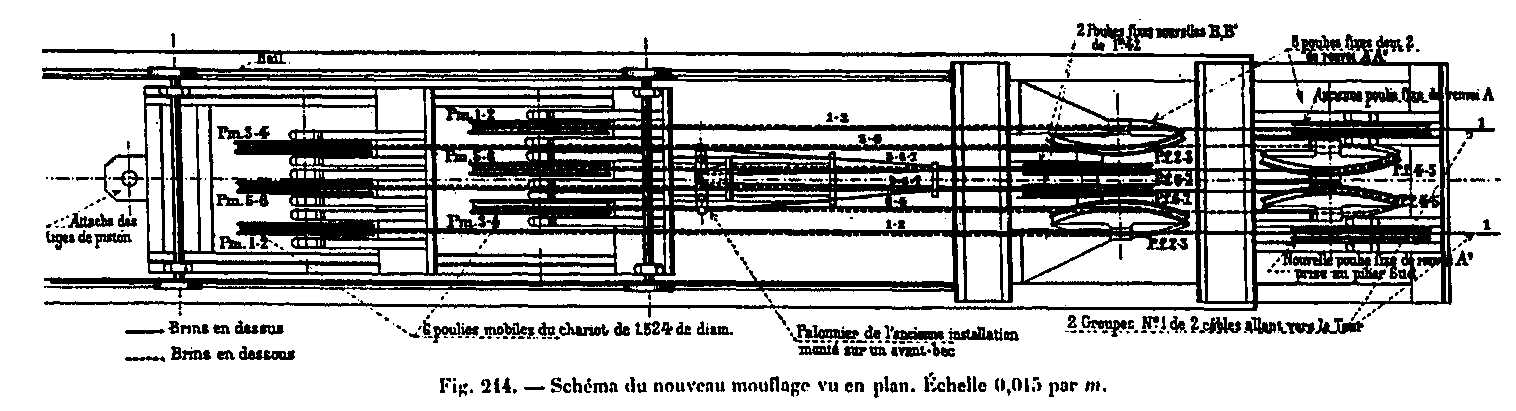
The mobile head carriage has undergone slight modifications resulting from the change of hauling. The 4 cables leading to the carriage were divided in pairs; each pair is muffled seven times on the pulleys. This arrangement, which makes it possible to tie the cables in the axis of the carriage, results in the addition of three fixed pulleys, as indicated in the diagram of FIG. 244. The pairs of cables received on the The pulleys A and A 'pass over the various pulleys and come to attach to the pallet, which is transferred from its former position on a spout adapted to the front of the movable carriage. The BB 'pulleys are new steel pulleys with a diameter of 1.42 m instead of 14 m which the other pulleys of the haulage. This decrease in diameter is necessary to allow the attachment of the dead strand on the rudder.
The support structure of the return pulleys has been placed on the 1st floor. The pulleys have kept about the same layout. However, the two motor cables on each side of the cab are returned by a pulley 3 m in diameter with 3 independent grooves, mounted on a special frame built on the side of the track. Both pairs of cables return to the motor guided by inflexion pulleys. The two counterweight cables, which are those of the old elevator, are returned from the cab to the latter which remains mitten with three strands. The total weight of the new counterweight is now only 15,000 kg instead of 20,660 kg. This weight includes 4478 kg of own weight and 10 522 kg of cast iron ballast.
Track and vehicle
The track is similar to that of the east and west pillar elevators and carries a double rack on which the claws of the safety brakes carried by the vehicle can hang. The vehicle, similar to that of these same lifts, differs only in the following points:

The cabin containing 80 passengers is on one floor. In addition, instead of being aluminum, it is made of steel. The chassis contains the same safety devices constituted in the same way, except however the recovery mechanism that would have been useless. The floor of the cabin is therefore directly attached to the frame rails.
Finally, the latter carries at its lower part the maneuvering station with its operating wheel, and its hand lever, controlling the triggering of the safety brakes. These brakes have a similar operation to that already described, and they are expected to play the same role in the case of the vehicle rescue maneuver. For this last maneuver and in order to introduce water pressure into the brake cylinders, two pipes are arranged along the track, one at high pressure, the other for evacuation. The high pressure water of the first pipe is provided by a small accumulator placed at the base of the pillar.
This accumulator has a 130 mm diameter piston giving a section of 133 cm3. The weight of the moving part is 10 000 kg, corresponding to a pressure per cm3 of 75 kg. The volume generated by a race is 13.27 l. To feed it, a hand pump with a pressure of 125 kg per cm3 is used. The water at this pressure can, at the exit of the accumulator, to cross the necessary height, which is about 50 m, and to overcome, once introduced into the brake cylinders, the effort of 9,000 kg corresponding to the cabin in charge on the 1st floor.
Otis Elevator Performance
As for the Fives-Lille elevator, it is possible to accept 60 seconds for the exchange of passengers, either on the 1st or on the ground; also counting 60 seconds for the single trip, the full round trip will take 4 minutes, which corresponds to 15 trips per hour. With the number of 80 travelers, the maximum return can be 1200 passengers per hour.
Modifications to the Edoux Vertical Lift
The changes made to this lift are intended to raise the number of 80 passengers instead of 65 when the cabins are about as charged and to give the cabins an average speed of 1,00 m. , so as to make about 10 trips per hour. This number of 80 and especially that of 75 were often made during the 1889 Exhibition; but under these conditions, the public, crowded into a cabin whose surface is less than 14 m2 or 5 to 6 persons per meter, is extremely embarrassed; the little freedom he has in his movements makes the entries and exits very slow. By restricting to 4 people per square meter, traffic is much easier.
But it is understood that the establishment of normal balance of the device is not changed, and that the difference in load can not exceed 4000 kg between the two cabins. To reach the proposed goal, the roof of the cabins was converted into imperial so as to receive 25 passengers on it, and only 55 passengers will be admitted inside, ie 80 in all.
Regarding the distribution of water, we saw in the study of this elevator that there was considerable pressure losses. It has been sought to reduce them by increasing the diameter of the pipes, by improving the distribution by the use of an Otis distributor and finally by modifying the head of the cylinders so as to facilitate the entry of the water. Finally, these load and speed conditions led to the study of a more advanced security device than the one previously used.
Cabin and Distribution Changes
The interior of the cabin receives no other modifications than the expansion of the doors. This width will be increased to 1.10 m giving an increase of 0.05 m. For the upper part forming imperial, we have been content to establish a light floor surrounded by a high railing mesh.
From the point of view of distribution, we have previously established that for a load difference of 4000 kg the speed does not exceed 0.50 m per second, because of the significant pressure drops that occur. In order to reduce them, the following modification has been made:
- 1. The line connecting the y-storey tank to the intermediate floor distributors was changed. The old pipe had an inside diameter of 200 mm; it has been replaced by a 250 mm pipe
- 2. The piping of the distribution of the intermediate stage, which was 150 mm in diameter, was replaced, in large part, by a pipe of 250 mm
- 3. Of the two Edoux dispensers, only one has been retained, the other being replaced by an Otis dispenser, giving greater flow and absorbing less load. This distributor is capable on its own to provide the service of the elevator, the former distributor becoming mainly a rescue device
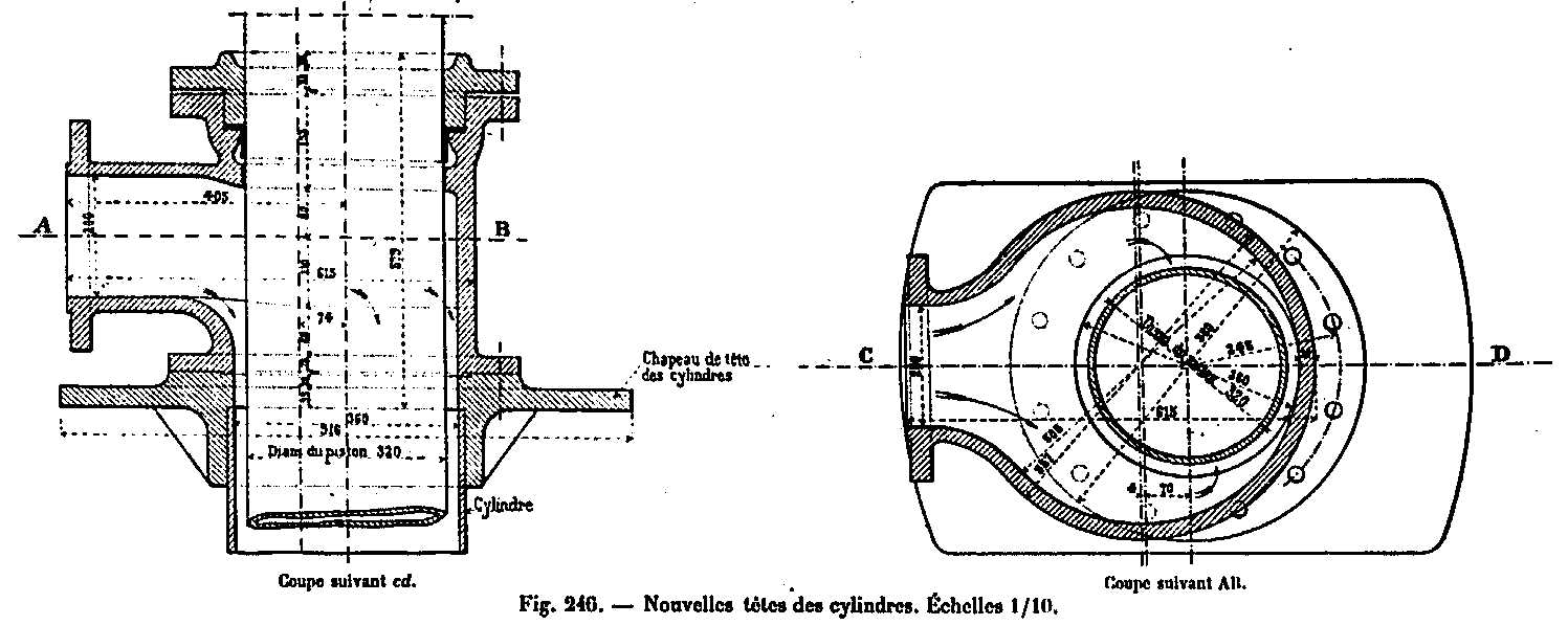
Finally, the cylinder heads were modified, which, by a defective introduction of water, absorbed a large part of the static pressure. This introduction takes place in the new heads, by a larger section, and with a more rational form, avoiding the liquid from hitting normally the walls of the plunger.
The piping of the new distribution has a diameter of 250 for the Otis distributor and 150 for the Edoux distributor.
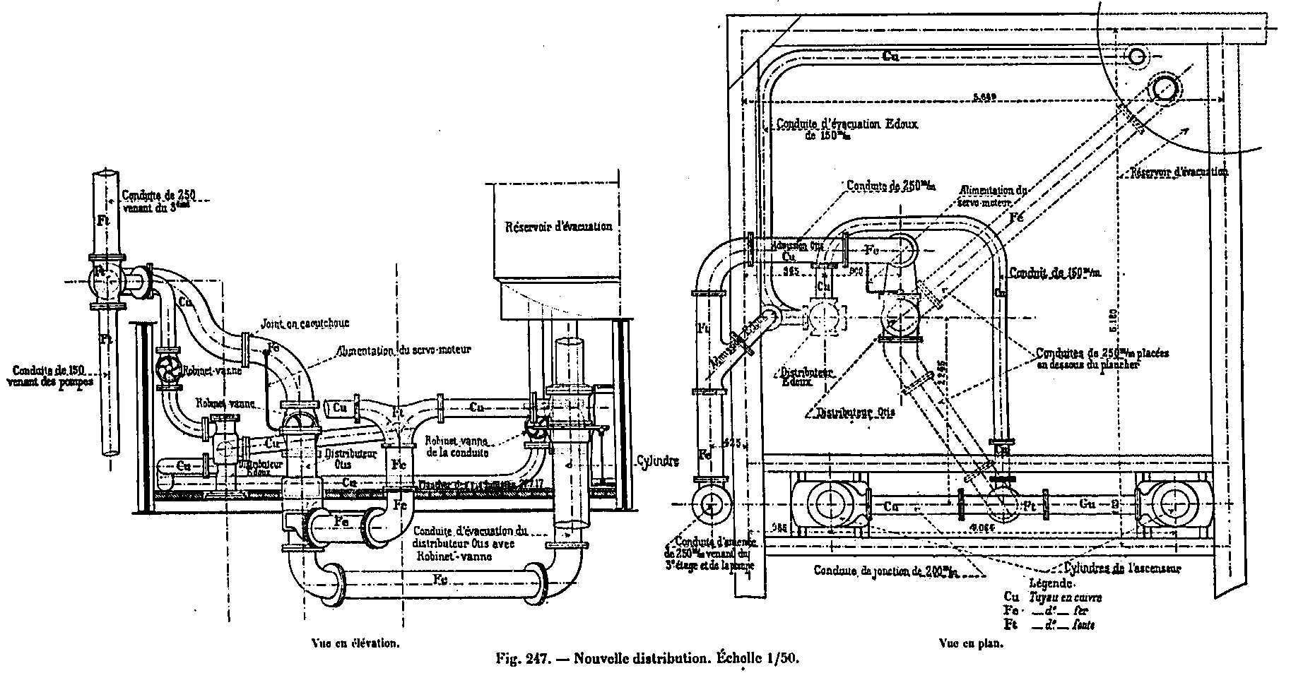
It is arranged in such a way that the water can be sent into the cylinders, either by each of the distributors, or both simultaneously.
Hydraulic safety brake
The use of the Backmann brake is very safe in the event of a cable break, especially if it is assumed that after contact of the friction cones the rotation of the spindle continues to occur during a period of time. very short time. Nevertheless, to increase it further and to allow the live power due to the fall to be absorbed in a longer time and to cause the various organs less fatigue, it has been considered useful to add to the elasticity of the washers Bclleville. whose stroke is only 80 mm, that of a hydraulic brake with a stroke of 900 mm. This significant increase of the stroke, which in total is 980 mm, considerably reduces the forces supported by the parachute fasteners at the time of its operation.
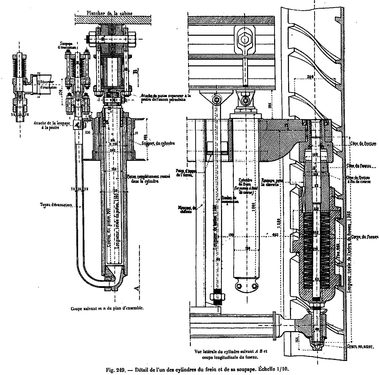
The hydraulic brake is composed of two presses placed symmetrically with respect to the axis of the chassis carrying the parachute (See Fig. 248).
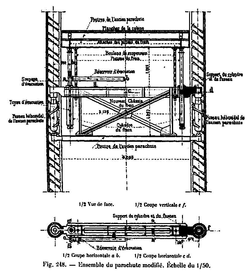
Each of the presses comprises a plunger 100 mm in diameter which, penetrating into a cylinder bored to 120 mm in diameter, delivers the liquid into a tank open to the open air by passing through an equilibrium valve provided with 'a spring. The piston of each of the presses is fixed by a hinge to the lower beam of the cabin (See Fig. 249). The cylinder rests by its head on a piece of steel, which carries at the same time, by means of an extension, the female cone of the spindle. This piece is riveted between the souls of a box beam braced with the support beam of the toad in spindles. The set forms a new perfectly rigid frame.
The chassis is suspended by means of two suspension rods 50 mm in diameter, hinged by a clevis carried by the lower beam of the cabin. These rods, during the retraction of the piston, can slide in the lower support so as to follow in its movement.
A steel pipe connects the bottom of each hydraulic cylinder with a drain valve at the end of the tank. The valve of this valve has a particular shape, so that at a determined lift correspond a given spring tension and a given flow rate.
The operation of the parachute is caused as before its transformation by the automatic stop of the helical spindles in the guide columns of the elevator. The automatic shutdown occurs when, as the acceleration of the cabin becomes larger than that of the spindle, the brackets attached to the cab slip into the lower and upper bronze bushings of that spindle; the friction cone then caps the upper cone of the spindle and stops the rotation of the latter. The spindle becoming fixed, the whole cabin continues to descend, the pistons penetrate the cylinders, by driving into the upper reservoir the liquid that filled them and forced to go through the evacuation valves, creating a resistance that gradually absorbs the living force. The washers Bclleville of the spindles also contribute to a certain extent.
In this movement, the suspension rods descend with the cab, through the upper beam of the chassis. The acceleration due to the fall of the spindle sliding on its propeller is 2.80 m instead of 9.81 m that it would fall freely; the force on the different organs corresponding to the absorption of the live power for a speed of 5 m does not exceed 21 000 kg on each side of the cabin, effort for which the various organs have been calculated, as we we saw for the old parachute.
East and West Pillar Stairs
These two staircases from the ground to the first platform were modified when they left the ground due to the existence of the accumulators of the new lifts, which during their uphill run come to occupy the site of the old stairs. . The starting flight bypasses the location of the accumulators and at a height of about 6 m joins the old staircase. This arrangement is shown for the West pillar in Figures 12 and 13 of the board XLVI.
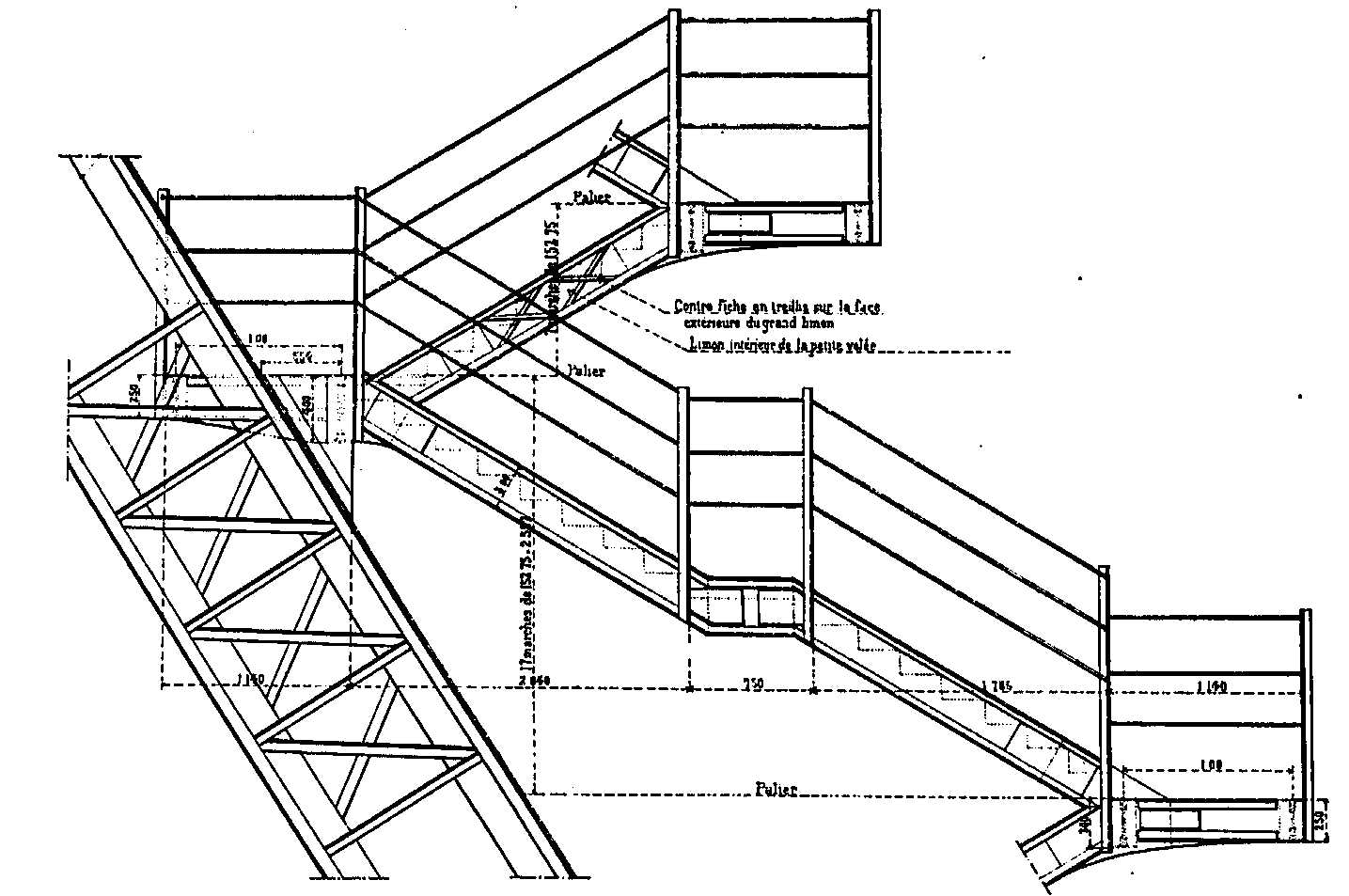
Staircase of the South Pillar
This staircase is intended for the descent of travelers from the 1st floor to the ground and to the ascent of the 1st to the 2nd floor, the rise of the ground on the 1st floor continuing to be done by the two stairs of the East and West piles. The new staircase, whose general layout is interesting, is established between the beams of the old Otis lift, on which it relies by projecting overhang the alternative flights which are counterfeit one by the other . It is composed of a series of revolutions, each of which includes a large and a small fly. The figure below is a diagram of one of these revolutions.
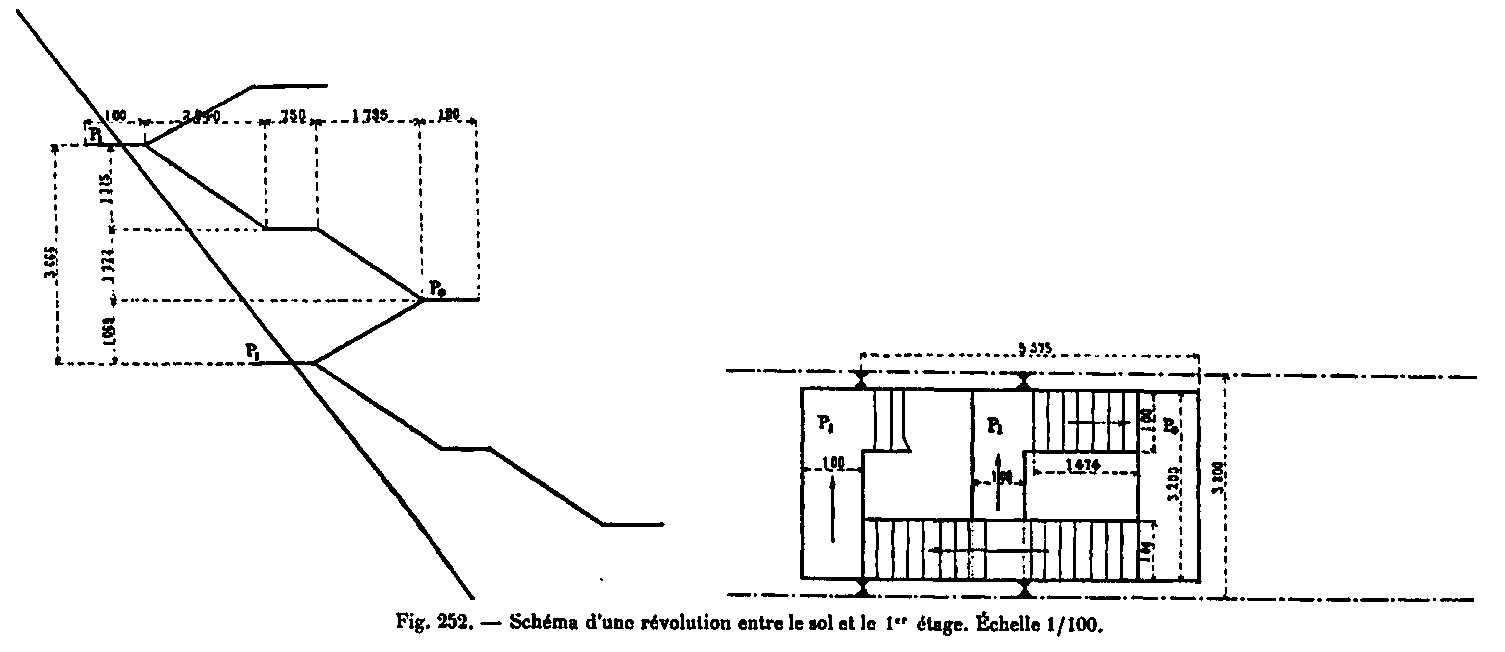
The bearings P1 are attached to the beams of the elevator whose axis-to-axis spacing is 3.80 m. From this landing a small flight ending at a P0 landing, outside the beams, from which the great flight joins the next P1 landing, and so on. For the part of the ground to the 1st, the staircase and the bearings have 1.00 m of width and the large flight carries a intermediate bearing with risers having a common height of 152.7 mm. The steps are in oak and furnished with a strip of iron. Each of the cantilever bearings P0 relies on the lower bearing P1 first by the small fly, then by a counter-slip placed in the plane of the outer silt of the big flight. As for the bearings P1 they are attached directly to the beams of the elevator.
From the ground to the 1st floor there are 14 revolutions of 3,666 m of height including 24 steps, plus a starting flight on the ground, of 21 steps, and an arrival flight of 7 steps, in all 564 steps. For the part of the 1st to the 2nd floor whose width is 1.50 m and whose large flights have no bearings, the revolutions, numbering 15, also have 3,666 m of height including 24 steps of 152,7 mm; but the width of these differs according to the position of the revolution on the road. The starting flight on the 1st floor includes 14 steps and the arrival flight on the 2nd includes 7, giving between the 1st and 2nd 381 steps.
The total number of steps between the ground and the 2nd is therefore 745. This new staircase replaces, by offering much more convenience, the old spiral staircases placed in each of the pillars, which are no longer accessible to the public.
Worthington pumps
The new layout of the engine room is shown in Figure 14 of the board XLVI. The machines are classified in three categories:
- Worthington pumps for elevators and restaurants.
- Generating sets for lighting and illumination.
- Condensers of these various machines.
Elevators Fives-Lille. The two Fives-Lille lifts are powered by two Worthington pumps labeled 14 and 15. Only one of these pumps operates in normal service, the other is a standby machine. The triple-expansion steam engine of each machine has its three cylinders in tandem.
- Diameters of the steam cylinders: 305, 457 and 737 mm
- Diameter of the four divers: 165 mmm
- Common race: 457 mmm
The inlet pressure is about 10Kg in the small cylinder. We have seen in the description of the elevator that in normal operation the suction is done at a pressure of 18 kg measured at the accumulator BP, and that the discharge is made to that of 52 kg measured at HP accumulators, either with a difference of 34 kg.
The pumps have been designed to take into account all pressure drops, so that they can operate at pressures of 10 and 55 kg measured on the machines themselves, with a difference of 45 kg. Their flow was calculated at the rate of 4500 l per trip of each of the two lifts, ie for 20 journeys per hour 90 000 l corresponding to 1500 l per minute.
The actual consumption of the elevators being only 4080 l, the 20 trips will take 81 600 l and the speed may be lower than the one calculated and that is the following one. Assuming for the divers a speed of 30 m per minute, the number of strokes corresponding to a double stroke of 0.457 m is 30 / (20 x 0.457) = 33 strokes. The power of these machines with the difference of 45 kg is (1500 x 450) / (60 x 75) = 150 horses.
In running mode, this power will not be reached due to reductions in flow and pressure deviation. Steam per hour horsepower consumption (not including purges and steam jackets) shall not, according to the contract with Worthington, exceed 11 kilograms. The low-pressure accumulators are filled when two small pumps, one of which is a replacement, start up. Each consists of two high-pressure cylinders of 114 mm diameter and two double-acting plungers 51 mm in diameter. Their common race is 102 mm.
Their power is about 2 horses and their flow of 60 l per minute. They can fill a low-pressure accumulator in one and a half hours.
Edoux Lift. The elevator Edoux to be able to make a greater number of trips than in 1889, is 10 instead of 7, it was necessary to increase the power of its pumps. Each of the two old pumps has a flow of 1100 l and walking simultaneously they could achieve the flow required for 10 journeys of 12 896 l; but as it was essential to have a spare machine, the group was completed by a new pump bearing No. 11 in Figure 14. This pump is triple expansion as the previous.
- Diameters of the steam cylinders: 203, 305 and 508 mm
- Diameter of the four divers: 178 mmm
- Common race: 381 mmm
With a count of 40 strokes, the flow must be 1300 l. The suction is 170 m and the discharge 318 m, including pressure drops, giving a gap of 148 m. These numbers are based on actual heights, 200 m at the suction and 278 m at the discharge and with 30 m of pressure drop at the suction and 40 m at the discharge. The power of this machine is (1300 x 148) / (60 x 75) = 42.75 horsepower.
By attaching it to one of the two old ones, we have a total flow of 1100 + 1300 = 2400 l, or 144 000 l per hour. At 12,896 l per trip, it is possible to make 10 trips per hour. Steam per hour horsepower consumption in rising water must not exceed 14 kg according to the market.
Otis Lift. The new Otis lift is powered by two new pumps bearing the No. 18 and 19. The first, which bears the No. 18, is a pump similar to the previous one bearing the No. 11. The suction is in a tarpaulin. 2 m deep and pumped into a tank placed at 121 m with a pressure drop of 10 m. The flow is 1400 l per minute. Steam water consumption (not including purges and steam hulls) is 14 kg according to the market.
The horsepower is (133 x 1400) / (60 x 75) = 41.3 horsepower. The second, which bears the No. 19, is capable of raising 750 l per minute under the same conditions as the previous one, ie with 131 m of load:
- Cylinder diameters: 133, 203 and 336 mmm
- Diameter of the divers: 140 mm
- Common race: 254 mmm
- Horsepower: (133 x 750) / (60 x 75) = 22 horses
- Steam consumption: 16 Kg per horse
By simultaneously running both pumps, the total flow will be 1400 + 750 = 2150 l per minute, or per hour 129,000 l. The water consumption per trip being 6 974 l, we can make a number of 129 000/6974 = 18.5 trips, which will certainly be above the needs. Only 14 to 15 are expected.
Food restaurants. As the last pump, there is more to report that that relating to the supply of spring water, bearing the No. 13, which was installed in 1889 for the service of restaurants.
Generator
The electric current for lighting, illuminations and flare is provided by four generators, namely: Two groups each formed of a 340 horsepower Carels pusher motor (N ° 24 and 25) making 325 turns and driving a 230,000-watt dynamo connected to it by a Zodel coupling, and two groups each formed of the old Sautter-type compound drumstorm engines of 70 horsepower, making 300 revolutions and each operating a new 50,000-watt dynamo (N ° 26 and 27). In normal operation, a Carels engine and a Sautter engine work together and are sufficient to provide service, the remaining two engines serving as a backup.
Condensers
The steam of all the engines is condensed by two large Worthington condensers of 6000 kg of steam each, and by the two existing condensers, each of which is capable of condensing 1200 kg of steam. Each of the large compound condensers is vertical and has the following dimensions:
- Cylinder diameters: 229, 406 mm
- Diameter of the pistons of the air pump: 508
- Common race: 305
Suction in a tank at 1.50 m and discharge in a tank at 3 m height. The power of each new condenser is about 7 horses. Each of them is intended to condense the vapor of: A pump for the Fives-Lille lifts. Two pumps for the Edoux lift (the old pumps are compound and consume 24 kg per horse-hour, their power is 36 horses). A pump for the Otis lift. A pump for feeding restaurants. That is to say all the steam pumps running simultaneously. The second group of condensers will be used for generators. There will be simultaneously a group of condensers of 6000 kg and another of 1200.
Generators
With the four Collet and Niclausse generators, each producing 1500 kg of steam per hour, two Babcok and Wilcox boilers were added each spraying 2000 kg of water at a pressure of 12 kg (N ° 1 and 2). The total possible production of steam per hour is therefore 10 000 kg. The generators are powered by the two small horses of the old installation and also by a third of the type Worthington (No. 9). Before the generators is installed a track for the cars that take the coke in a cargo hold in one of the corners of the pile. The two Babcok boilers and a Collet boiler will be operated during the day; in the evening, a boiler Collet and more. The production of steam at 12 kg pressure will be 5,500 kg in the day, which corresponds to a regular service of about 600 horses.
The consumptions, per day of 12 hours, are established as follows: For the water used for the condensation, a weight equal to 20 times that of the condensed vapor is planned. This weight of vapor being estimated for a full day of exposure at 63,800 kg, the weight of water used for condensation will be 1,276,000 kg per day. This water being paid to the City 0.125 francs per cubic meter, the daily expenditure during the Exhibition will be 1276 x 0.125 = 159.507 francs. For coke, consumption is forecast at 7 kg per kg of vaporized water. This consumption for one day of the Exhibition will thus be 63800/7 = 9100 Kg. Coke being estimated at 13.50 francs per ton, the daily expenditure of fuel can be foreseen at 9100 x 33.50 = 304.85 francs . The total daily expenditure on water, fuel and maintenance materials will therefore average about 500 francs.
The lighting of the Tower becomes fully electric; it is divided into three distinct categories:
1. The actual lighting which includes the lighting of all establishments on the Tower, platforms, stairs, elevators, etc .; to this category are also attached the lighthouse and floodlights of the upper platform.
2. Illumination which includes the exterior decor of the Tower; she draws the frame completely with 4 108 incandescent lamps with 10 candles placed in tinplate reflectors.
3. The conflagration which is intended to replace the old conflagrations with the flames of Bengal. It will be provided by means of 30-amp arc lamps equipped with colored glasses; it will work alternately with enlightenment.
Lighting
The actual lighting will consist of eight main circuits from the machines. The first tour will include French and Russian restaurants. Second, English and Dutch restaurants. The third, the lighting of the first platform by arc lamps. The fourth, bars, shops, stairs and elevators. The fifth, the offices and the kiosks with soil tickets, the second and the third floor. The sixth and seventh, the spotlight. The eighth, the lighthouse.
The set will form a total of 1300 incandescent lamps of 10 candles, 20 arc lamps of 10 amps 3 arcs of 100 amps. Incandescent will operate at 120 volts at lamps and 130 at machines; each lamp will consume 3.5 watts per candle; the consumption for 1500 lamps will be: 1500 x 3.5 x 10 = 51 000 watts.
To this consumption, it is necessary to add the loss allowed in the lines which is of 10 volts. The electromotive force at the terminals of the board being of 130 volts, the loss allowed will be: 10 x 100/120 = 8.3%, that is for the 54 600 watts, 4352 watts. The total current to be supplied will be 54,600 + 4,532 = 59,132 watts. The lighting of the first platform by arc lamps will comprise 20 arcs of 10 amps mounted by 2 in tension. The watts consumed by this circuit will be: (20 x 10) / 2 x 130 = 13000 watts.
The lighthouse consumes 100 amperes at 65 volts; the surplus electromotive force available will be used in a resistor placed on the board. There will be 2 Mangin floodlights, one of 90 cm in diameter, the other of 1.50 m. As for the lighthouse, the lamps will be mounted in bypass, and the surplus of electro-motor force will be used in resistances, it will take 300 amps to power these 3 devices at the rate of 100 for the lighthouse, about 60 for the projector of 0 , 90 and 140 for the projector of 1.50 m. The wattage will be: 300 x 130 = 39,000 watts.
The total consumption of the actual lighting will therefore be: 59,132 + 13,000 + 39,000 = 111,132 watts.
The illumination
The illumination of the Tower will be divided into 13 ignition circuits. There will be 1 circuit per side up to the first floor, 4 circuits. The fifth will include the first floor gutter. The sixth, the amounts of the gallery of the first floor. The seventh, the cabochons of the gallery of the first floor. The eighth, the coronations of the arcades of the gallery of the first floor. The ninth, the part between the first and the second floor. The tenth, the gutter of the second floor. The eleventh, from the second floor to panel 18. The twelfth, from panel 18 to the consoles under the third floor. The thirteenth, the summit. The circuitry will include 4,108 10-candle lamps whose consumption in watts was set by the contract of Mr. Beau, general contractor of this lighting, to 3.2 watts per candle, giving a total of 4108 x 10 x 3.2 = 131 456 watts. The loss allowed online is, as for lighting, 8.3%, The lost energy will be: 131 456 x 8.3 / 100 = 10 911 watts for a total consumption of 131 156 + 10 911 = 142 387 watts.
The burning
Flashing will be ensured by reversing arc regulators equipped with spherical silver-plated copper reflectors and colored glasses. There will be 6 lamps per pillar on the floor, 24 lamps. As much on the first floor. 16 on the second floor. And 8 in the middle. A total of 72 lamps. These lamps will be 30 amps and mounted in pairs in series. The total expense will be 72 x 30/2 x 130 = 140 400 watts.
Power needed to power the Eiffel Tower
The illumination and the conflagration having to work alternately, the maximum expenditure will be of 111,132 + 142,387 = 253,519 watts. The current will be provided by four compound gensets as follows:
1. Two groups each consisting of a 340-horsepower triple-expansion Carels motor operating, using a Zodel elastic coupling, a 230,000-watt multi-pole dynamo (type M. 200). The unit rotates at a speed of 325 rpm.
2. Two groups each formed of a Sautter engine of 70 horsepower compound each operating a dynamo of 50 000 watts at 300 revolutions per minute. In normal operation, a Carels machine and a Sautter machine producing 230,000 + 50,000 = 280,000 watts together will be enough to service.
The other two groups will serve as a replacement. These machines will be assembled in quantity on the bars of a distribution board by means of circuit-breakers automatically cutting the circuit in the event of an unexpected stop or slowing down of a machine. The board will also carry all measurement and distribution devices for the different lighting, flare and illumination circuits.
The total horsepower available in the engine room is 340 + 70 = 410 horsepower for both machines running simultaneously. There are many as a reserve. The number of 280,000 watts indicated for these machines gives, at a rate of 660 watts per horse, a substantially equal number, 280 000/660 = 425 horses. In normal operation, we will use 253 519/660 = 383 horses.
In addition to these main groups, a 10-horsepower motor, powered by an 8000-watt Sautter dynamo, capable of powering about 200 10-candle lamps, was installed for daylighting and service purposes. 3.5 watts per candle.
Renovations of 1937
The Universal Exhibition of 1889 saw the construction of the Eiffel Tower, a masterpiece of French genius exhibited at Le Monde. That of 1900 caused various modifications to this tower, it was necessary to make it more efficient, safer too, more modern. But there was a third world exhibition in Paris, much later: That of 1937, just before the war. At that time they were no longer so called, its official name was "The International Exhibition of Arts and Applied Techniques for Modern Life". But it was neither more nor less than another of these universal exhibitions that were organized around the world at that time.
It is for this occasion that the Eiffel Tower undergoes new transformations, just like a large number of buildings in Paris. We begin to remove the decorations dating from 1889, they were out of fashion. Exit therefore the decorative surcharges of the buildings of the first floor , which are also largely reworked. Then the lighting was reviewed. More efficient, it allows visitors to better circulate on the tower at night. The four restaurants, one of which had been transformed into a theater, are destroyed.
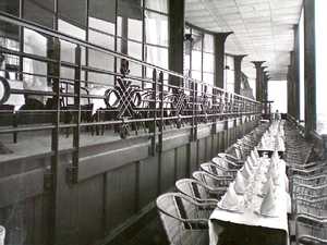
Gallery of the first floor in 1937
Gallery of the first floor in 1937
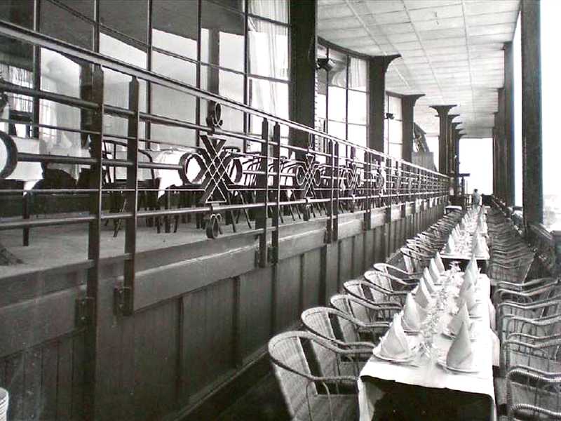
Gallery of the first floor in 1937
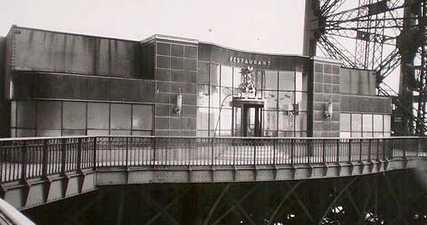
Restaurant of the Eiffel Tower in 1937
Restaurant of the Eiffel Tower in 1937

The facade of the restaurant of the Eiffel Tower, in 1937
In parallel in Paris, some Parisian buildings are improved: The former palace of Trocadero is demolished, replaced by the Palais Chaillot, the Palais de Tokyo is built. During this year the countries of the world came to install pavilions in Paris. Two were particularly interesting: that of the USSR, on the right of the Champs-de-Mars was facing that of Nazi Germany, on the left.
Renovations of 1982
1982 is also the year of the renovation of the tower. Unlike the Statue of Liberty, which the Americans have never really been able to maintain, the Eiffel Tower has always been carefully maintained. The planning of the painting was perfectly followed, with the notable exception of the period of the first world war, where it was necessary to wait 3 years more. But almost a century later, the tower could be analyzed and modified, because the initial calculations of Maurice Koechlin and Emile Nouguier, the designers, were perfectible with the modern means.
The first floor in 1982
The first floor in 1982
View of the first floor in 1982, between the renovations of 1981 and 2011

The Ferrié flag in 1981
The Ferrié flag in 1981
View of Ferrié Pavilion facade, 1981
Major works were therefore launched on the Eiffel Tower between March 1981 and September 1982. They were supervised by Yves Lafoucrière, chief engineer. So we lightened the structure by 1343 tons by removing many useless beams, then we replaced the stairs and lifts that became obsolete. Finally we added security elements to deal with the explosion of tourists, the eighties corresponding to the beginnings of mass tourism in Europe. In fact, the older ones still remember the protective grilles of the 80s, which were rather low. Nowadays, it is almost impossible to climb them, even going up the stairs. In addition to these works, officials repainted in golden color the names of the 72 scientists who adorn the first floor of the tower. Exactly on the first floor the restaurant "Le Jules Verne" is installed, it is at its opening a gourmet restaurant.
This renovation was accompanied by an anti-corrosion treatment and a painting campaign on the entire tower, and finally the renovation of the lighting system, which will consist for a few years of 352 sodium projectors. This new lighting started in 1986, the time to install everything.
The inauguration of the new installations on the first floor of the tower took place on September 23, 1982 by Jacques Chirac, then mayor of Paris. The photo opposite shows it at the shop.

Jacques Chirac inaugurating the Eiffel Tower
Jacques Chirac inaugurating the Eiffel Tower
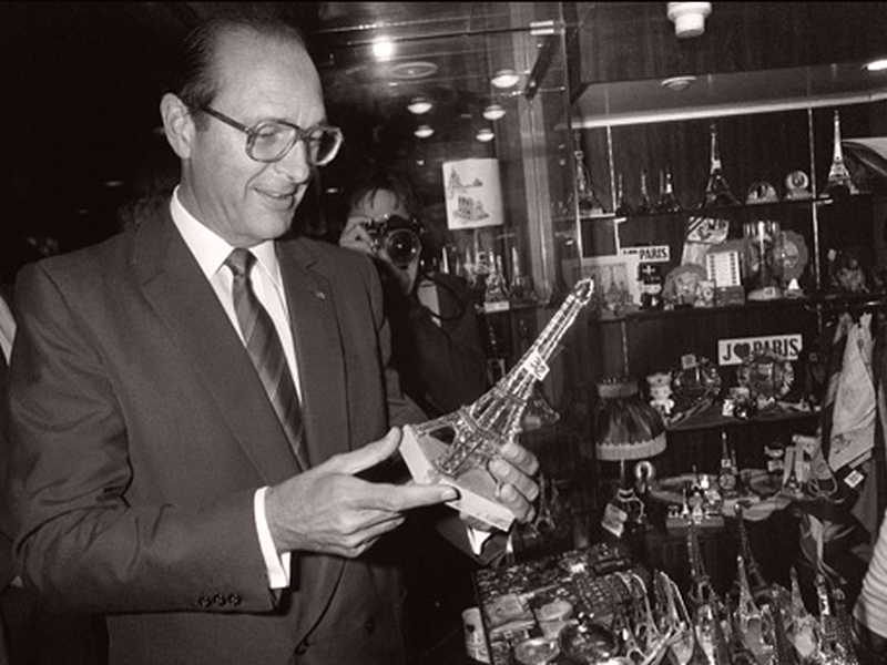
Jacques Chirac inaugurating the Eiffel Tower, September 23, 1982
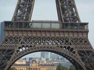
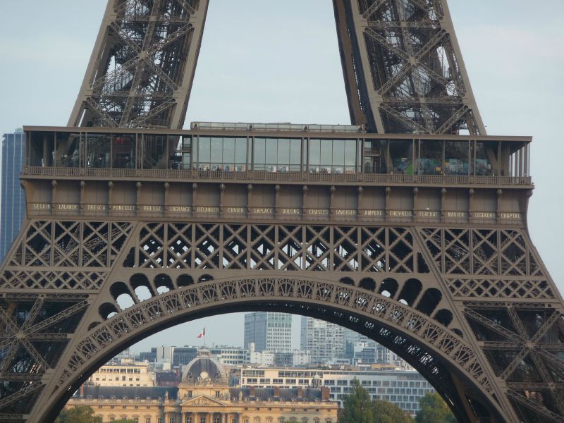
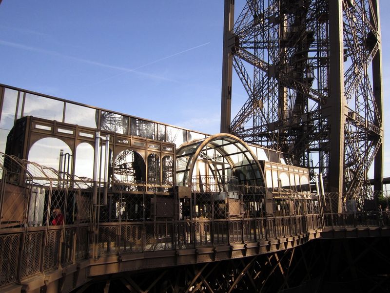
The new pavilions are much more modern than the previous ones, which were inherited from the construction of the tower. They are rather flat, very long, they go from one pillar to another (or almost). Their aspects are peculiar to the time they were built, ie a rather technological, cubic style. Note that the color was that of the tower, there was no difference between these buildings and the structure itself, unlike what exists today. The 3 pavilions were essentially glazed parallelepipeds that inserted between the pillars. The gallery on the first floor was also straight, with a perfectly flat roof and regular pillars that crisscrossed the facade of the monument. It should be noted that this gallery highlighted the names of scientists who are registered in the consoles, on the main beam from the floor. Also the restaurant before a nice bow in front of its entrance, it was a bit like a signature.
All these installations were removed in 2011, replaced by more modern and better arranged pavilions.
Renovations of 2011
In 2011 the first floor underwent a new facelift, the buildings therein were modernized. A glass floor has been built there, which is a tourist attraction, much like London Bridge, London, or CN Tower, Toronto. It is the architect firm Moatti-Rivière who designed this floor, for a budget of 23 million euros. The idea was to completely transform the first floor, very dated 80s. It must be said that it became important because the visitors stopped there less and less, preferring largely the 2nd floor, even, for those who could, the 3rd. Yet the available space is much larger than on the other floors, despite the large hole in the center of the floor.
So, with the aim of modernizing this floor, a competition was launched in 2009 by the SETE, the Eiffel Tower Exploitation Company. It was won by the firm Moatti-Rivière, located in the 11th arrondissement of Paris, which was given the responsibility for the design and implementation of the upstairs developments, in partnership with the company. Bateg. They therefore made a clean sweep of the facilities on this floor: Everything was dismantled and returned to the ground, only the floor remained that was reworked. The construction took place while the tower was open to the public, so it was necessary to cohabit the workers and tourists, which was not very easy to do. The work was placed under the control of Jean-Pierre Baron, head of the works department at Bateg.
Construction constraints
There were several constraints to take into account during this renovation. The first, which has already been mentioned above, concerns the presence of the public on the site. Indeed, there was no question of closing the tower for the duration of the work, it would have been too long, so it was necessary to close areas for work while maintaining a certain attractiveness to the tower, so leaving it available some of the facilities.
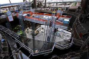
The renovation project
The renovation project

General view of the renovation project of the Eiffel Tower in 2011
Another constraint concerned the monument itself. The Eiffel Tower is a monument classified world heritage of humanity, (included in the name "Edge of the Seine"), but it is especially registered with the Historical Monuments, which makes it impossible to install the yard like we would like it. It is impossible, for example, to drill holes in the beams to attach lifts or safety rails, everything must be done without affecting the structure of the monument. And this constraint was not the easiest to implement.
The third constraint concerns the height. Establishing a site of great importance for several months at 56m height is not easy. It was necessary to use a system of notching to not damage the monument, but it is especially the installation of the security which was important. The triple mesh nets were fixed by mountaineers at night. They are supposed to recover anything that could fall from the yard, from the hammer to the smallest bolt. Scaffolding was installed, but here too, climbing to 60m is not easy. The four pillars are also flanked to the floor of the first floor of the tower to evolve a mobile platform at this height, platform that served as both freight elevator and scaffolding work.
Another constraint was the weight of the items to go up and down. Indeed, it is particularly important that the Eiffel Tower does not undergo a variation of its weight at the end of the work, it must always weigh the same thing. So, to make sure, each mounted piece was weighed, its weight being added to the total structure of the tower. We reduced the weight of dismantled parts, of course. This weighing work was very important and took a long time on the site.
The improvements
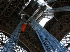
The renovation project
The renovation project
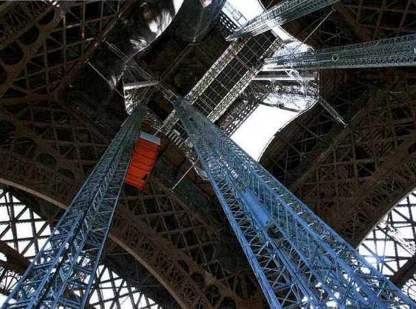
The scaffolding put in place in 2011 for the renovation of the first floor
The central hole, which was perfectly square, saw its edges curving towards the center, forming a sort of wave. The railing has become a series of perfectly transparent glass plates, 2m wide and 2m high, held by relatively thin pillars. These glass plates have the characteristics of being inclined towards the void, which makes it possible to stick to it, facing the void.
The 3 pavilions have been completely redone. They are now curvaceous, they follow the shape of the pillars, which allows a better integration to the very structure of the Eiffel Tower. Mostly made of glass, they are very transparent, only the walls on the sides and the ceilings and floors are opaque, but the general impression is that they are really open. As the entire floor has been cleared, these transparent pavilions accentuate the impression of height. Moreover this impression is confirmed by the glass floors, 8 in number, which advance on the empty tower.
This floor is quite successful, it has various museum locations, restaurants, shops. The set is really modern. We can imagine that this is not to everyone's taste, since we lose a little technology specific to Eiffel, but this is precisely what could be blamed on the former development of the first floor, that of 1982.
Is the glass floor really solid?
The answer is yes, yes, and yes again! His technical description, given in the magazine "Le Moniteur" of May 31, 2013, explains it:
In order to invite visitors to stay on the first floor, the architects imagined to make them experience the central vacuum thanks to a glass floor installed on the periphery of the central void, completed with guardrails also glazed. The new floors, which will replace elements used during the 1982 renovation, will consist of three layers of glass whose resistance has been increased thanks to a Sentyglass film. The top layer of tempered glass coated with email on 25% of the surface for antiglare, will be sacrificial: In case of breakage the lift will remain ensured by the lower layers of hardened glass. These glazed elements will rest, on one side, on the historical lattice girders of the Eiffel tower, named "beams of 30m". On the other side, they will be fixed on the torsion beam which serves to maintain the railings. In the longitudinal direction, the windows are based on new IPNs via an EPDM seal and are fastened by cover-clamps. The glass railings, high of 2m65 and inclined of 17 ° towards the vacuum divide in two: They are in glazing trifeuilleté up to 1m10 and in bifeuilleté above. They are maintained thanks to caps-compressors on vertical uprights T-shaped themselves fixed on the torsion beam. The latter is set back from the historic beam that forms the shore.
How were the glass facades of the pavilions constructed?
The double-curved facades of the three pavilions represent an architectural feat. "In France, it is impossible to make double curvature insulating glass façades," explains Alain Moatti, from the Moatti-Rivière architecture firm.

The renovation project
The renovation project
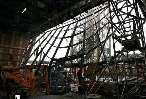
Establishment of the facades of the pavilions, in 2011
See also: