
Principle of construction
Suppose for a moment that we have arranged in the faces a simple lattice forming a wall resistant to the shearing forces of the wind, whose components are P ', P ", P' '', P" "(Fig. 8). It is known that in order to calculate the forces acting in three pieces cut by a plane NM, it suffices to determine the resultant P of all the external forces acting above the section and to decompose this resultant into three forces passing through the three cut bars.
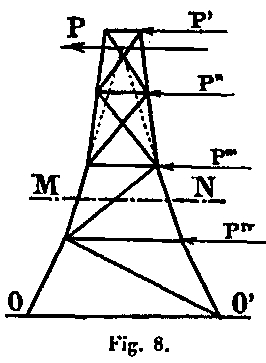
If the shape of the system is such that for each horizontal section MN, the two extended rafters have their intersection in the direction of the external force P, the effort in the lattice bar will be zero and we can remove this bar. It is the application of this principle which constitutes one of the peculiarities of the system employed for the construction of the Tower, at least in its lower half, and which determines its external form. It allows, by eliminating all trellises in the greater part of its height, to constitute it by four insulated uprights, simply connected at the level of 1st and 2nd floor by horizontal belts. One is thus led to bend the direction of each of the elements of the uprights in a curve which must be confused with the pressure curve, if it is proposed to have zero cutting forces; but this is only feasible for a single hypothesis.
Since we propose to examine several hypotheses on the distribution of wind, we will have to draw an average fiber approximating the average of the pressure curves, so as to minimize the bending moments that may occur according to one or the other hypothesis. Let us remark that the curve of the pressures corresponding to a wind of a constant intensity over the whole height of the Tower is independent of the absolute value of this intensity and consequently that this intensity has no influence on the very form of the Tower. Since the pressure curves do not pass exactly at the center of the uprights, ie they do not completely merge with the average fiber, bending moments and shear forces result which must be calculated.
Intensity of the wind
We have admitted several hypotheses:
a. The first gives rise, in general, to maximum fatigue: it is that of a wind of 300 kg per square meter acting uniformly over the entire height of the tower. According to the generally accepted formula, P = 0.12V2, in which P is the pressure per square meter and V is the speed, this pressure of 300Kg corresponds to a speed of 50 meters per second, which is that of a great hurricane. Whatever may be the uncertainty in the measurement of such velocities, it may be certain that no such has ever been observed in our regions, at least near the ground; if they were realized, they would give rise to real disasters. A pressure of 150Kg overturns the railway trains, as has been observed at Rivesaltes, and that of 270 Kg is the maximum allowed by the ministerial circular of August 29, 1891, for the calculation of the works of art. This last figure is the one that is generally adopted in these calculations.
We must say however that gusts of 40 meters of speed have already been indicated by the instruments placed at the top of the Tower, all reservations made on the accuracy of these indications. They correspond, according to the formula, to pressures of 200 kg per square meter. But, as will be said later, we have reason to think, from direct pressure experiments, that the above formula gives too high results and that the coefficient of 0.12 should be reduced to 0.09, which would actually give winds of 50 meters, 225Kg of pressure per square meter and for winds of 40 meters, 150Kg of pressure. Our assumption of 300Kg would correspond to a wind of 60 meters per second or 216 kilometers per hour, which was never observed. Assuming it happens at a certain point at the top, it would decrease rapidly as it approaches the ground.
b. This consideration has led us to examine a second hypothesis which is also excessive, although closer to reality: it is that of a wind reaching 400 kg at the summit and gradually decreasing to 200 kg at the surface of the ground. At any point, located at a height h above the ground, the intensity of the wind will be200Kg +— x h.
With the coefficient of 0.12, the corresponding velocities are 58 meters at the top and 40 meters at the base; with the coefficient of 0.09, the speeds would be 66 meters and 47 meters. These two hypotheses lead to the extreme limits of the coefficients of work and they are what we used to determine the sections of the various elements of the Tower. Nevertheless, once the sections determined it seemed useful, to enter the maximum probabilities of the practice, to seek what become the extreme coefficients in the case of a wind varying from 300 Kg at the top to 100 Kg at the surface of the ground.
Surfaces offered to the wind
Surfaces exposed to the wind are determined by assuming that the wind normally acts on the faces in a horizontal direction; which amounts to evaluating them by counting them in their vertical projection. Solid surfaces (floors, galleries, restaurants, etc.) were naturally counted in their entirety. For the determination of the recessed surfaces, we have admitted that the first wall normal to the wind is wholly struck by it at its full intensity and that the neighboring walls which it partially protects are also struck entirely, but by a wind of which the intensity is diminished in the ratio of the voids to the full of the anterior wall. That is to say that for the same intensity of the wind, if s1, and s2 represent the surfaces of the pieces encountered by the wind on the first and the second face, S1 the surface of the first face assumed to be fully full, we will have to count for the second face a surface of S2 = s2 x (S1 - s1) / S1.
We applied the same method to determine the areas offered to the wind by the lattice bars and struts which are box-shaped and whose 4 corner angles are joined together by a small lattice. This hypothesis is no longer exact when the distance between the first struck surface and that which is behind becomes great; because, as a result of this distance, the wind resumes its primary intensity. Also in the middle part between the first and the second platform, we admitted that the wind also hit all the amounts. At the base of the Tower, because of the large number and importance of the connecting pieces that bring the crossbowmen together, we have gone even further: we have admitted that the four posts were full or more exactly that they were replaced by their full projection on the vertical plane and that in addition they were all equally struck. This method of calculation leads to almost the same results as the application of the previous rules, as we have been able to realize, but it is simpler.
Division into elements
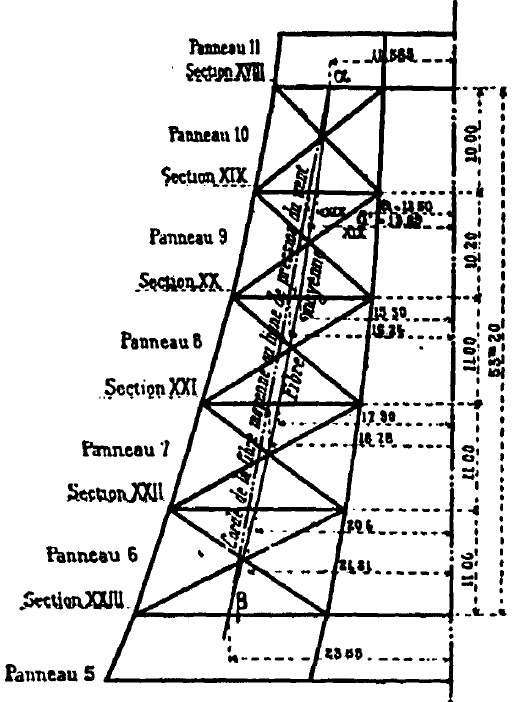
In the following calculations, we will admit that the action of the wind is concentrated in a certain number of appropriately distributed points on the whole height of the Tower. To this end, we divided the Tower by horizontal planes into 28 elements or struck surfaces. Each of them corresponds to a wind force that we will apply to the center of the element.
This division of the Tower into elements is indicated in the board XXXIII. Each running element comprises two adjacent half-panels and since the heights of two successive panels never differ very much from each other, the center of action of the wind on an element can be considered as situated on the horizontal spacer which separates the two panels; thus on each of these spacers is concentrated half of the forces acting on the two adjacent panels
Element surfaces, elemental wind forces and corresponding reversal moments
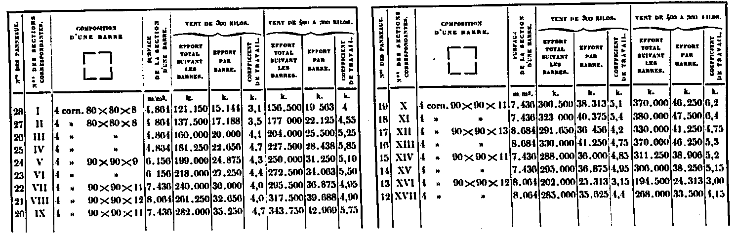
We have reported in an appendix the detailed calculation of the surfaces of each of the panels and we give in the table below the areas corresponding to each of the elements 0 to 28, as well as the forces P due to the wind in the two hypotheses, obtained in multiplying the surfaces by 300Kg and 200 + 200/300 xh Kilos. We will write in the same table the heights k of the center of the elements above the base as well as the corresponding reversing moment PA.
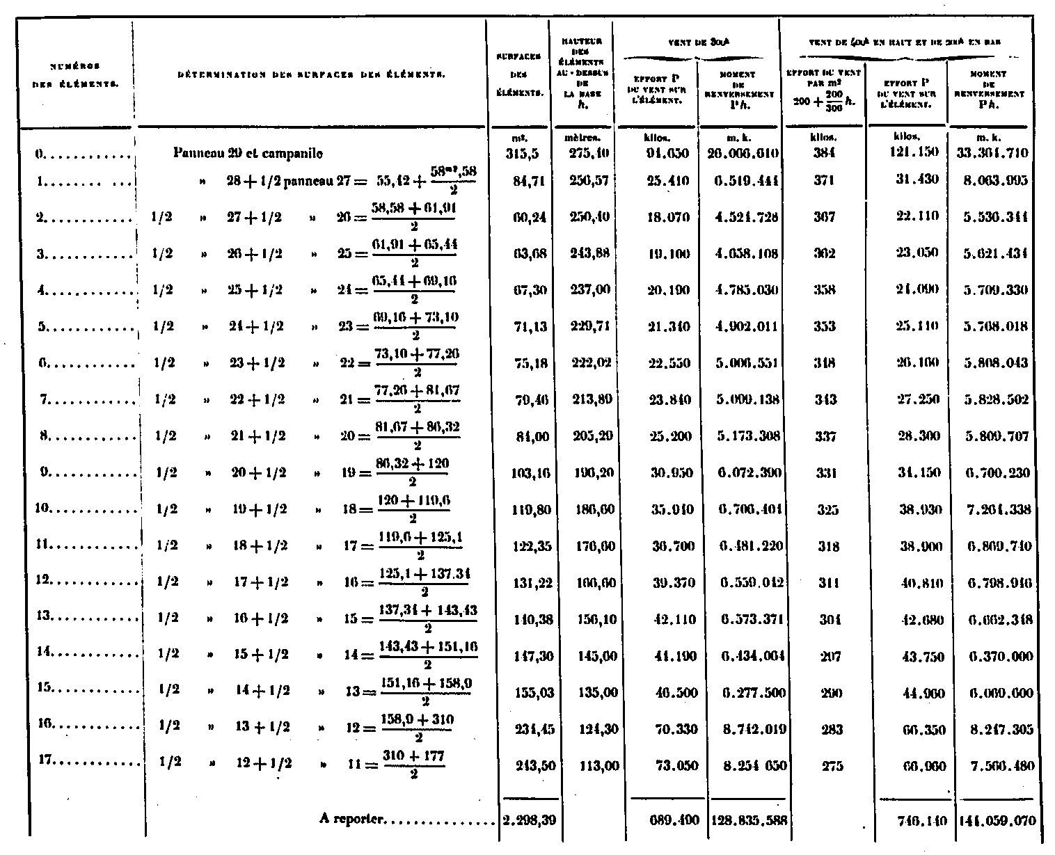
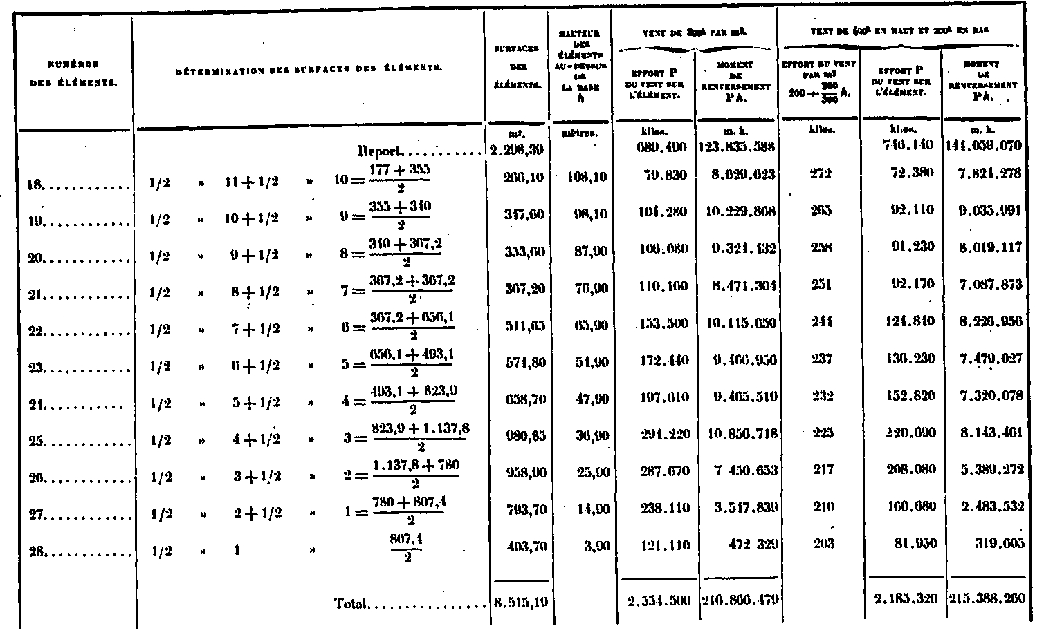
It results from this table that the whole Tower has a wind surface of 8515,19, that the wind, in both cases, exerts efforts that are respectively 2554 tons and 2185 tons, finally that the moments of total reversals are respectively 216,866 tons and 215,588 tons-meters; that is to say, from the point of view of this effect, the two hypotheses are nearly equivalent. In the first hypothesis, the center of action of the wind is located at a height of 216 866/2 554 = 84.9m above the supports; in the second 215 388/2 185 = 98.55m.
We are now, as the efforts are known, to examine the effect on each part of the Tower. But for that it is necessary to consider successively either the upper part, that is to say the one situated above the 2nd floor, in which all the uprights are joined together; the lower part, that is to say the one going from the 2 nd floor to the floor, in which the four uprights are distinct and are only joined together by the belts of the 1st floor. and the 2nd floor.
Calculation of the molecular forces due to the wind in the upper part
crossbows
The crossbows of each of the faces being made integral by their trellises, the computation of the forces is done simply by means of the bending moments.
Let M be the bending moment of all the forces of the wind acting above section MN, ω the section of the 3 crossbowmen of the face cc hit by the wind or that of the opposite face c'c '; e the horizontal spacing of the centers of the opposite faces, and E the force in one face; the value of the latter will be M / e and the working coefficient R1 = E / ω assuming that the rafters are substantially vertical and that the b'd 'crossbowers, neighbors of the neutral fiber, have a moment of negligible resistance. By making the calculation for the region adjacent to the 2nd floor, in which the bd crossbowmen are separated and introducing the exact moment of inertia, taking into account these crossbowmen, it would be easy to recognize that even at these points, their influence is negligible and only affects the working coefficient by about 0.2 kg.

The curve of the bending moments is plotted in the board XXXIII, fig. 3, for each of these two hypotheses, using the force polygons, FIGS. 1 and 2. Since the length scale is 0.002 per meter and the polar distances are 800 000 kilograms, the moments for the moments are scale of 0.002 / 800 000 = 0.0025 per 1,000,000 kgm. They can be directly read on the sketch.
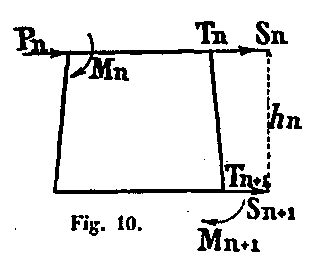
To calculate them numerically, we use the following consideration: Let two sections Sn and Sn+1, separated by the height hn of the panel, in which Mn, and Mn+1 are the bending moments, Tn and Tn+1 are the shear forces and let Pn be the force of the wind in the section Sn.
We have Mn+1 = Mn + (Tn + Pn) nn ou Mn+1 = Mn + Tn + hn this allows each moment to be deduced from the previous moment, by adding the product of the shear force at the point considered by the height of the panel. Thus the figures in the following table from section I to section XVII have been established. As a verification, we have also determined directly for this section XVII, the sagging moment corresponding to each of the two hypotheses; it is the sum of all the partial moments due to the forces of the wind acting above this section; we will first give this picture.
Calculation of the sagging moment in section XVII
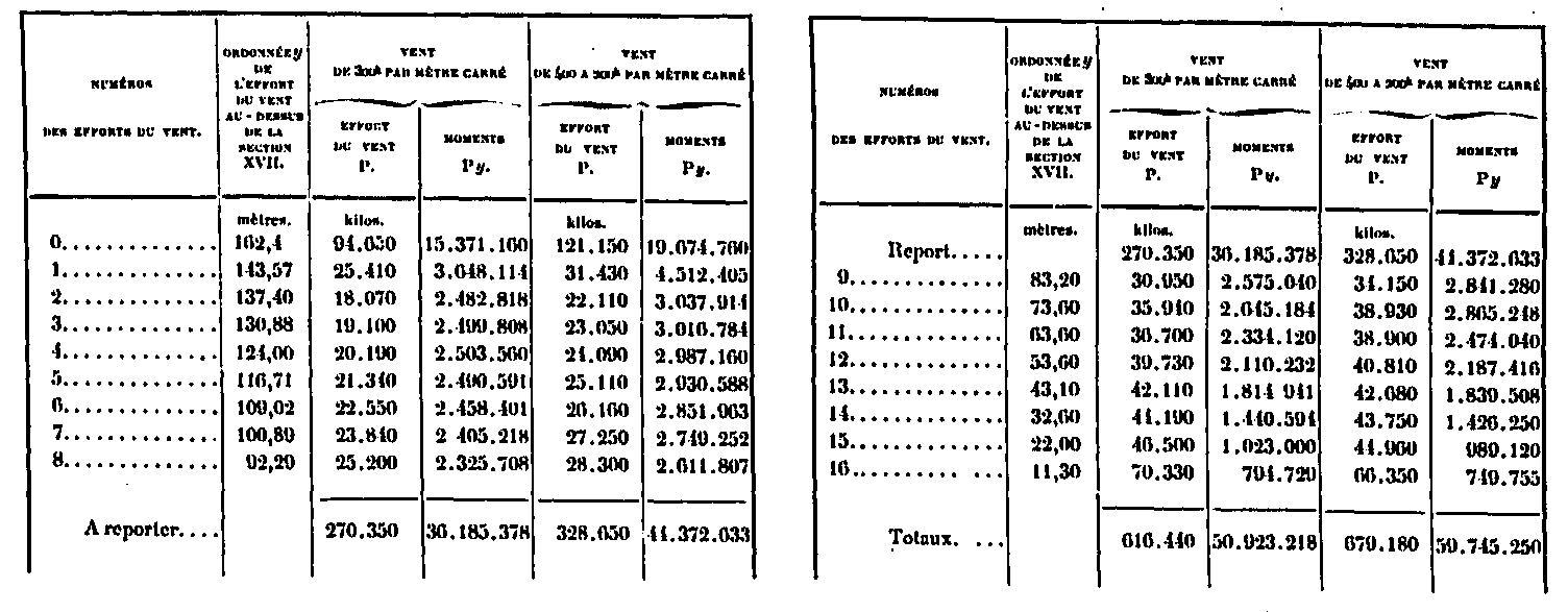
The moments in this section are 50 923 218m. kg. in the 1st hypothesis and 59 745 250m. kg. in the second. In the table below we have summarized the elements of the calculation for each of the sections, such as bending moments and shear forces, as well as the forces in the faces and the working coefficients in the rafters.
Calculation of bending moment, shear force and working coefficient in the rafters for each of the actions above section XVII
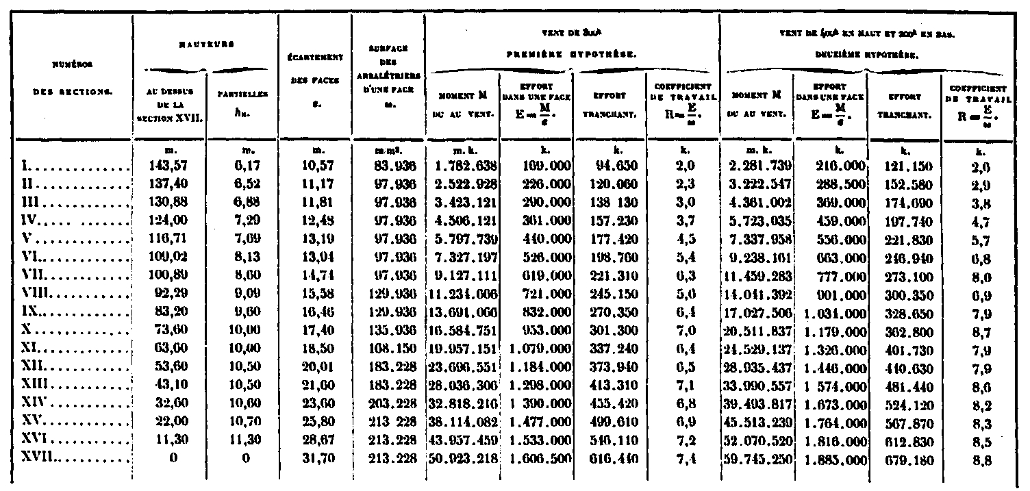
The maximum work due to the wind in the rafters takes place in section XVII where it reaches 7.4Kg and 8.8Kg per square millimeter.
lattice
We will admit that the forces of the lattices cut by the same horizontal section MN are equally distributed between all the bars of the resistant walls. We will therefore calculate the effort F according to these bars as if one of them, AD for example, were alone, and since the number of the resistant bars is 8, ie 4 per wall, it will be admitted that the effort for each bars is F / 8.
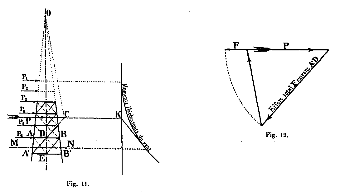
The force F is obtained by decomposing the external force into 3 forces passing through the rafters A'A, BB 'and by the bars A'D.
It suffices (Fig. 11) to extend the directions AA ', BB' to their meeting point O, and the direction A'D to the meeting point C with that of the resultant forces external P, then join CO and build the polygon forces of Figure 12; its closing line parallel to A'D gives the effort F sought. The position of the external force P itself is obtained for each section MN, by means of the funicular polygon of the bending moments due to the wind (Fig. 11), by determining the intersection K of its first vertical element with the extension of the cut element.
We could have taken the bar DB 'and we would have obtained the same effort in a similar way, because of the symmetry of the bars A'D and DB'. As for the bars AE or EB, one would obtain slightly higher efforts, but little different so that it is necessary to take them into account; it is for this reason that we considered only the bar A'D and that we gave to others the same section. For the clarity of the overall figure, board XXXIII, we have reduced the force F on the direction of the force P. (Fig. 12). The table below gives for each section, in the two hypotheses, the value of the effort F, F that of the effort in each bar, the section of it and the corresponding work.
Calculation of forces and working coefficients in lattice bars above section XVII
The average working coefficient is around 5 to 6 kilos.
Calculation of molecular forces due to wind in the lower part
Principles of calculations
Let P1, P2, P3, ... the different components of the wind acting on the Tower at heights h1, h2, h3, ... above the base AA'.
Suppose we trace the funicular polygon of these forces, for the lower part only (Fig. 13), using the force polygon (Fig. 14) in which the forces are carried horizontally and whose polar distance is V.
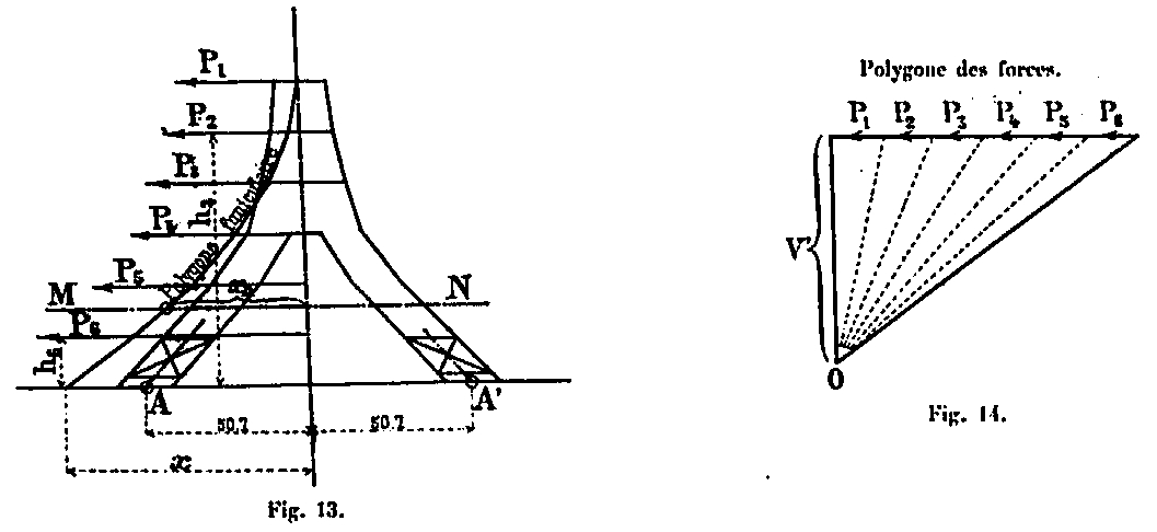
M = ΣPnhn the total reversal moment of all wind forces P1, P2, P3, ... relative to AA base ' of the tower. The moment in any section MN is Mn = xn V', at the base it is M = xV', expressions in which xn, and x represent the abscissae of the funicular polygon in the MN section and at the base (Fig. 13). As for the polar distance V, it is arbitrary: to have that corresponding to the funicular polygon passing by the supports, it is enough to put M = 50,7 V, 50,7 being the abscissa of the center of the amounts at the base; from which we draw V = M / 50.7. This funicular polygon is then at the same time the curve of the pressures of the forces of the wind.
As we only determine the efforts for a single amount, it is easier to carry in the polygon forces, instead of the total efforts P, a quarter of these efforts to directly obtain the effort in an amount.
The curve of the pressures corresponding to these forces P1 = P1/4, P2 = P 2 / 4, etc., should be drawn with a polar distance v = V / 4 (Figures 15 and 16).
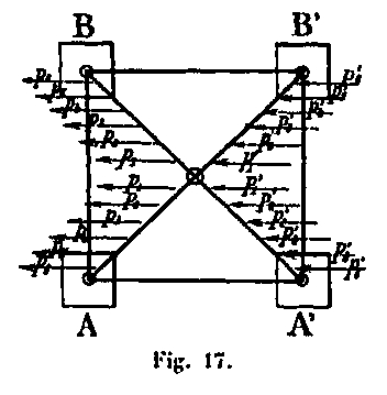
For a section MN (Fig. 15), the external force q on an upright is given in the force polygon (Fig. 16). The forces in the uprights are tension forces q in the first two amounts A 'and B' struck by the wind, and symmetrical compression forces q in the other two uprights A and B (Fig. 17). We only consider the amounts where the wind produces compressive forces in addition to those produced by the own weight of the construction. The external force q produced in section MN:
- An N compression force acting in the average fiber of the amount
- A shearing force T normal to this average fiber.
- Bending moments from the fact that the pressure curve does not pass through this section at the same point as the average fiber, that is, the axis of the amount.
Compression and shear forces
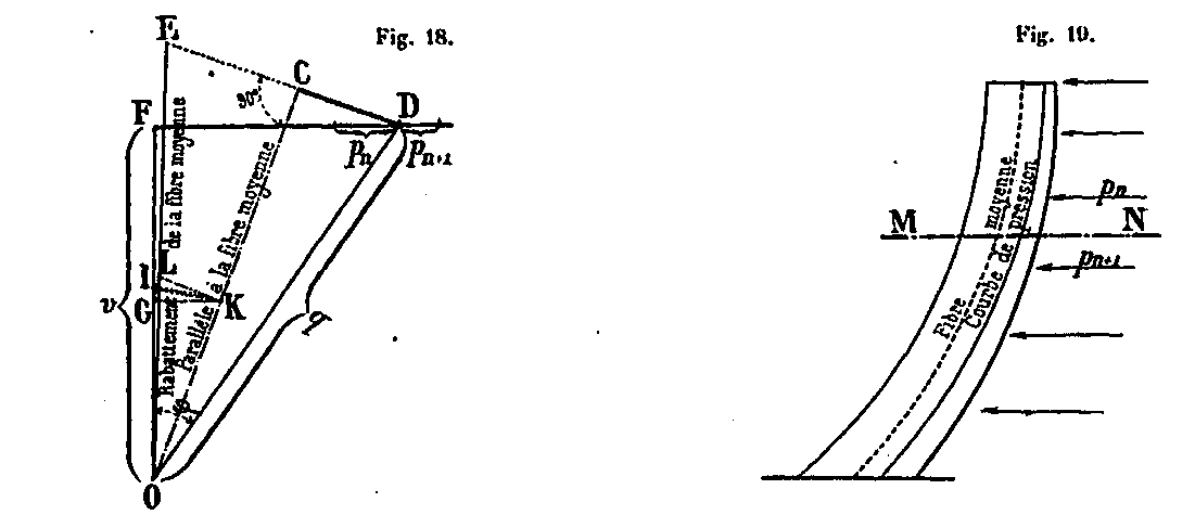
These forces are obtained for each section by decomposing in the force polygon (Fig. 18) the external force q in two forces, the one OC parallel to the direction of the average fiber in the section MN, the another normal CD at that same direction.
This stress CD is the shear force T that will be decomposed according to the directions of the lattice bars of the panel cut by the section MN; we will have the effort produced by the wind in these bars.
As for the compressive force OC, as the amount is inclined according to the diagonal plane of the Tower, this force acting in a vertical plane is still to decompose in the direction of the amount in the face perpendicular to the figure ( Fig. 18). This decomposition can be done very simply as follows:
From the pole O of the force polygon as center, we draw an arbitrary arc from the point 1 located on the vertical of the pole to the meeting point K with OC. From the point K, we raise a perpendicular KL to OC and point I, a perpendicular IL to KL; we thus obtain the point L, intersection of these two lines. By decomposing the component OC in the direction of OL, one obtains the compression force N * = OE in the amount. The CEO angle is indeed equal to the tilt angle of the average fiber in one of the faces of the upright.
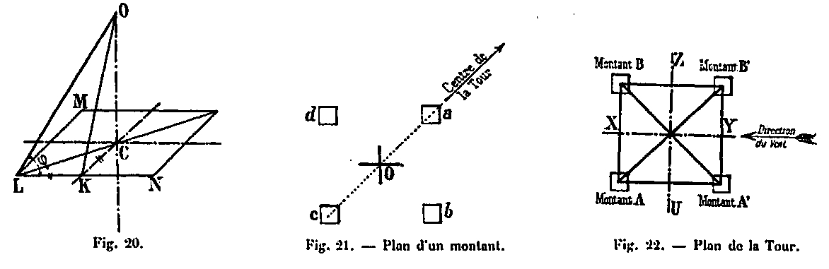
Indeed, since MN is a horizontal plane (Fig. 20), to have OL, knowing OK, it is enough to have the length KL = KG and to take it on a perpendicular to OK raised to the point K. Now, as we We have shown previously that, with respect to vertical loads, G is on the horizontal led by K, and KG reduced to KL gives the point L sought (Fig. 18). We see immediately that the construction indicated above, by means of the perpendiculars KL and IL, is reduced to this one; it graphically defines the L point very exactly. This force N which acts at the center O of the amount in the section MN, is distributed equally between the four rafters a, b, c and d (Fig. 21) and gives in each of them a compression force E1 = N / 4.
The pressure curves that correspond to the two cases of wind overload have been plotted in the outline of the board XXXII, fig. 3, using the force polygons fig. 1 and fig. 2, which have been determined only for the sections of the lower part. The polar distance of each of them is equal to a quarter of the reversal moment M divided by the half-spacing of the uprights at the base, or 50.70m. In the first hypothesis, we have seen that the moment of reversal is 216 866 479 m. k. We therefore have vn = I / 4 x 2l6 866 479 / 70.70 = 1 069 350 Kg.
In the second hypothesis, the reversal moment is 215 388 260 m. k. and the polar distance is vn = I / 4 × 215 388 260 / 50.70 = 1 062 050 Kg. Shear forces are also determined in the same polygons.
Bending moments
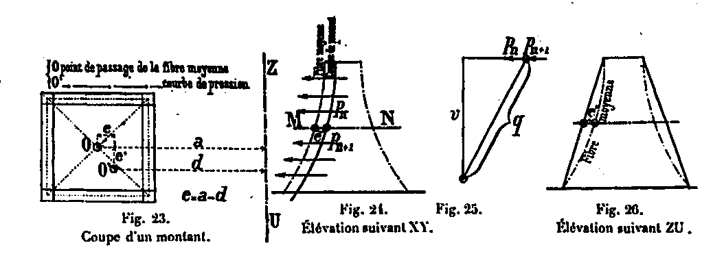
The couple that produces them can decompose in two; one μ which acts in a plane parallel to the direction of the wind XY, the other transversal μ ' which acts in a perpendicular plane ZU (Fig. 22). The first is due to the misalignment of the external force in the direction of the wind direction, and the second to the misalignment in the direction normal to the wind direction, as shown in Figures 23, 24, 25 and 26 below. below.
Determination of moments parallel to wind direction
For the determination of these moments, it is necessary to have projections of the pressure curve on the XY and ZU planes. The first is given by the funicular polygon (Fig. 15, p.34) corresponding to the horizontal forces of overturning (board XXXII, Fig. 3). By calling the horizontal distance of this pressure curve from the average fiber for any section MM '(Fig. 27), the bending moment of the external force F is equal to F & θ ;, θ being the normal distance: as a result of similar triangles formed with the force polygon, e / θ = F / v, so F θ = ve. We will designate this moment in the vertical plane by &mu ;, we will have μ = ve.
This moment must be projected according to the face of the amount. For this, it suffices to represent the moment mu, acting in the plane XY, by its representative axis and to compose it with the moment mu; sought, whose axis is perpendicular to the plane of the side B of the amount; we have μ1 = μ / sin α, α being the inclination of the face of the upright on the horizontal (Fig. 28).
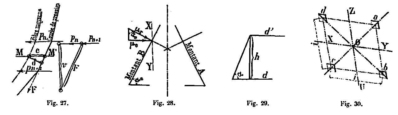
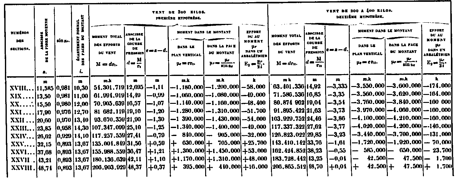
It is easy to calculate the expression μ / sin α. Indeed e = a - d (Fig. 23), that is the difference between the abscissa of the average fiber, with respect to the vertical axis in the vertical plane of the uprights, given by the diagram of the elevation (board XXXI) and the abscissa of the pressure curve which is calculated at using the moments of reversal. As M = dv, we get d = M / v.
The values of M are calculated numerically using the preceding table, as we did for the upper part, by the same formulas Mn + 1 = Mn + Tn + 1 + hn. As for the angles α, they are determined on the same diagram of the elevation by their tangent (Fig. 29): h being the height of the panel whose d and d 'are the abscissae, tg α = h / (d - d ') from which the values of sin α.
Finally v is the polar distance, equal to V / 4, of the force polygons (board XXXII , Figs 1 and 2).
As for the effort produced in the rafters under the action of the moment mu; it is equal for one face to E = I / 2 x μ where i denotes the normal spacing of the rafters in their folded faces (Fig. 30). The table below summarizes all the elements for both assumptions.
Calculation of the forces in the rafters due to the bending moments acting in the plane parallel to the direction of the wind.
Regarding the signs, we always give the positive sign to the couples that turn around the center O of the amount in the direction of the clockwise. For a positive value of &mu ;, this value of E, is a compression on the rafter a and a tension force on the rafter c, both when the wind acts in the XY direction and when it acts in the UZ direction.
On the other hand, for the rafters b and d, the stress En represents either tension or compression, depending on whether the wind is acting in one or the other of these directions. We have therefore, supposing positive the compressive forces:
- In the crossbowman a, an effort + E = μ / 2i
- In the crossbowman c, an effort - E = μ / 2i
When the wind acts in the XY direction, we have:
- In the crossbowman b, an effort + E = μ / 2i
- In the crossbowman d, an effort - E = μ / 2i
When acting in the UZ direction, the forces in these two crossbowmen change their sign.
Determination of normal moments in wind direction
The forces due to the transverse bending moments are determined in a similar way.
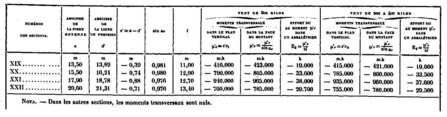
The sagging moment μ of the section MN, produced by the misalignment of the external force in the vertical plane UZ normal to the wind, is equal to the product of the polar distance v of the force polygon by the horizontal spacing e 'of the average fiber and the rope (Fig. 26) that is, we have μ = ve '; this moment acts in the UZ vertical plane.
To obtain the corresponding moment folded in the face, we will do a decomposition similar to that which has already been done for the pair μ XY plane parallel to the wind direction. We thus find in the face of the amount a moment which is equal to μn '= μn' / sin αr and which produces in the crossbowmen a, b, c, d efforts Eα = μ' / 2i. These efforts are always positive for the crossbowman a, and negative for the crossbowman c, assuming μ positive. That is, we have:
- In the crossbowman a, an effort + E = μ / 2i
- In the crossbowman c, an effort - E = μ / 2i
Quand le vent agit suivant la direction XY, on a :
- In the crossbowman b, an effort + E = μ / 2i
- In the crossbowman d, an effort - E = μ / 2i
When he acts in the direction of UZ, the efforts in these last two crossbowmen change their sign. These moments were calculated for sections XIX, XX, XXI and XXII in the table below by the method we have just indicated. In all other sections, they are void. In the direction normal to the wind, the efforts are transmitted according to the rope of the average fiber between two belts. The abscissa d of this string, as well as the abscissa of the average fiber, are shown in Figure 31 above and are found in the table which also gives the values e '= a - of those of sin α, of i, as well as the moments μ' = ev and μ = μ' / sin αn which correspond to the two hypotheses of wind overload, and the efforts En = μ ' / 2i.
Calculation of the forces in the rafters due to the transverse moments.
Calculation of total wind forces in crossbowmen and maximum working coefficients
We now have all the elements to summarize the total forces in the rafters, that is to say the longitudinal forces following the average fiber and the forces due to the misalignment torque. These efforts, assuming positive moments mu + and positive mu, are:
- In the crossbowman a, an effort E4 = E1 + E2 + E3
- In the crossbowman c, an effort E4 = E1 - E2 - E3
When the wind acts in the XY direction, we have:
- In the crossbowman b, an effort E4 = E1 + (E2 - E3)
- In the crossbowman d, an effort E4 = E1 - (E2 - E3)
When the wind acts in the UZ direction, we have:
- In the crossbowman b, an effort E4 = E1 +-(E2 - E3)
- In the crossbowman d, an effort E4 = E1 + (E2 - E3)
As the wind can act either on one face or on the other, we will choose the case which gives on the rafters b or the greatest efforts, which are thus of:
- EN = E1 + (E2 - E3) si E2 - E3
- EN = E1 - (E2 - E3) si E2 - E3
These efforts are summarized in the table below for both assumptions.
Calculation of the total forces due to the wind in the rafters.
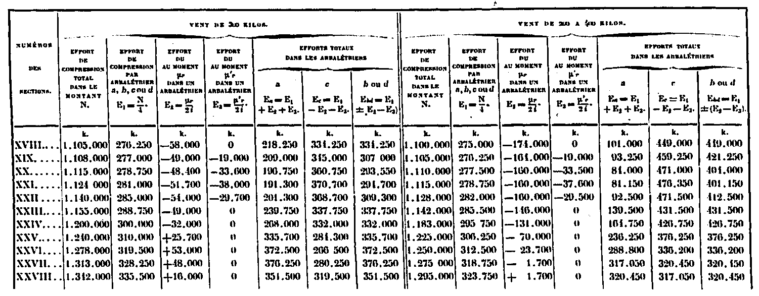
It is easy to deduce the working coefficient of the rafters, whose section is known; this is what the table below gives us:
Calculation of the maximum working coefficients due to the wind in the rafters.
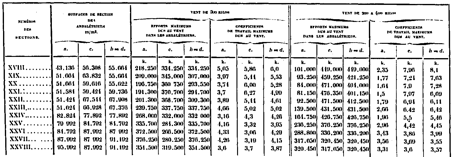
These coefficients will have to be added to those due to the own weights.
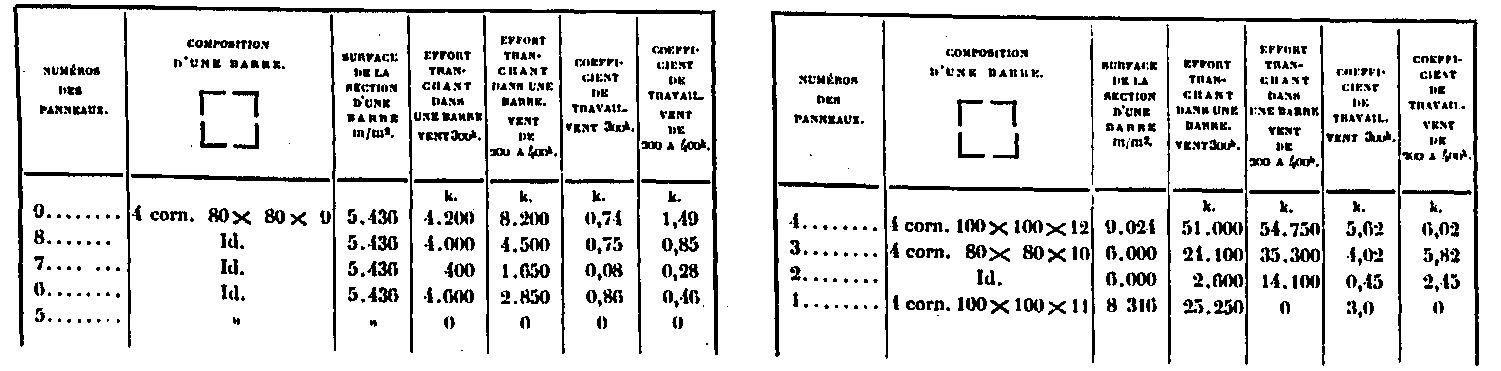
Calculation of wind forces in lattice bars and corresponding working coefficients
These efforts, together with the corresponding coefficients of work, are summarized in the table below:
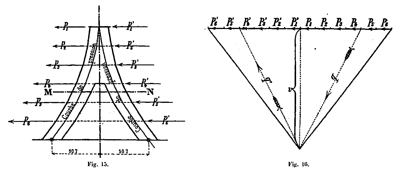
We have admitted in the preceding calculations the hypothesis of a wind striking the Tower normally on one of its faces; we shall now examine the case of a wind acting in any direction and show that the forces which it produces are equal to or lower than those already calculated. For this purpose, consider a quadrangular prism ABCD of width a, and a height equal to unity (Fig. 52).
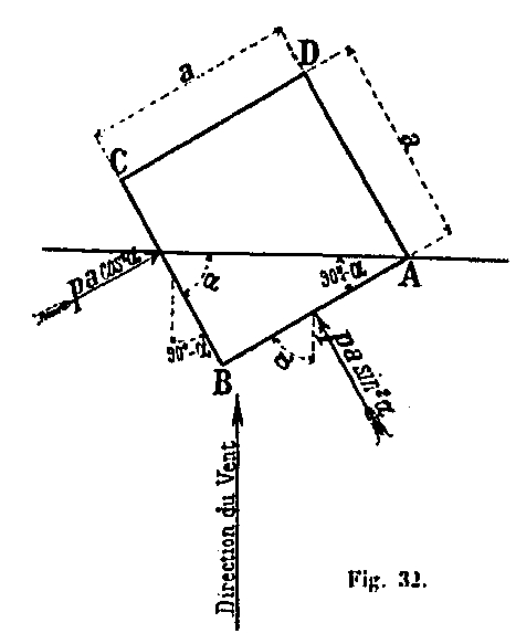
If a wind of intensity p normally acts on one of its faces, it produces on the prism a force pa. When, on the contrary, the wind meets the face AB of the prism at an angle α, it produces on this face a normal force which has the value pa sin α. The corresponding force of the wind on the face CB is equal to pa cos α.
So, if P1, P2, ... Pn represent the forces of the wind acting on the Tower normally at one of its faces, a wind of the same intensity, striking the face AB at an angle α, will produce on this face of the efforts P1 sin α, P2 sin α , etc. and on the normal side CB efforts P1 cos2 α, P2 cos2 α, ... Pn cos2 α.
It will be sufficient, therefore, to examine separately the forces produced by the forces P2 sin α normal to the AB face and those given by the forces P cos2 α normal to the face BC, then to sum it to have the total forces due to the wind.
See also: